4
© Copyright 2015 Zoeller
®
Co. All rights reserved.
General Information
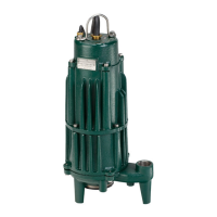
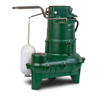
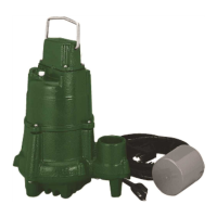
GRINDER PUMP DESCRIPTION
1. Pumps are constructed of class 30 cast iron protected with powder
coated epoxy for long life when pumping sewage in submersible
applications. The cutter assembly is comprised of stainless steel
components hardened to a value of 55-60 on the Rockwell C scale;
a star shaped cutter and a precision ground at disk. Cutting action
takes place with the rotation of the star cutter at 3450 RPM against
the stationary cutter plate (see page 11).
2. The cutter mechanism on the model 7011 is bidirectional, enabling
it to cut in either direction. A control panel with the reversing feature
will alternate the pump’s rotational direction with each duty cycle.
The cutter mechanism on model 7012 and 7013 is single directional.
3. Pump motors are available in single and three phase design. Single
phase motors require a Zoeller approved starting relay, starting
capacitor and a run capacitor, which are mounted in a control panel
(ref. page 8).
4. The 7011, 7012 and 7013 Grinder Pumps are dual seal and have seal
leak probes. Single phase units have an internal thermal overload.
Three phase pumps have a thermal sensor.
5. Three phase pumps require overload protection in the control panel.
6. A Grinder Pump is an intermittent duty pump designed for pumping
sanitary sewage. It is not a dewatering or trash pump.
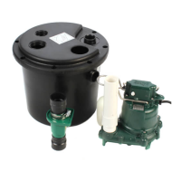
FIELD ASSEMBLED INSTALLATION
1. Installation and piping instructions are included with the control panel,
rail system and basin instructions. If pump is being retrotted to an
existing rail system, accessory parts may be required. Consult the
factory and advise make and model of rail system being used.
2. Refer to the appropriate Indoor/Outdoor prepackaged instructions
on pages 6-9 for more information on system installation.
3. All electrical connections including pump to control box and power
supply to control panels must comply with the “National Electrical
Code” and applicable local codes. Conduit and panel enclosure
openings must have a gas and watertight seal. Installation of
electrical panels, conduit and connections should be made by a
qualied licensed electrician. A UL Listed potting kit, P/N 10-2350,
is available from Zoeller Company.
4. A properly sized disconnect switch, supplied by others, shall be
installed on the service side of the pump and control panel.
5. When installing a pump with a check valve, or a rail system with
a check valve, you must give the pump case time to ll to help
prevent air lock when lowering the unit into the liquid. The pump
case has an air vent located behind the discharge. This air vent is
across the pump housing mounting surface and must be cleaned
before each reinstall. An extra air vent hole 5 mm (3/16") may be
drilled in discharge pipe below the check valve to help prevent air
lock. This drilled hole must be cleaned before each reinstall. After
the pump is installed, run the unit submerged to assure the pump
case is lled (Water should come out of 5 mm [3/16"] diameter hole).
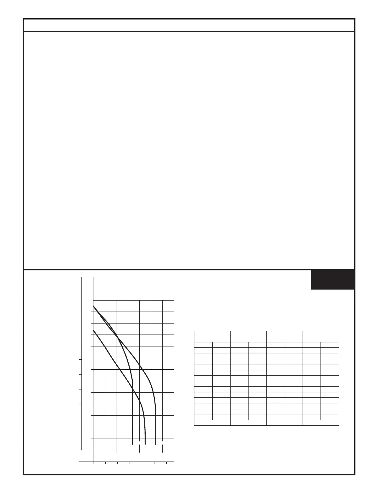
FIGURE 1.
016532
HEAD CAPACITY CURVE
MODEL 7011/7012/7013
0 40 80 120 160 200 240
70605040302010
0
10
4
8
12
16
20
130
70
60
50
40
30
20
GALLONS
LITERS
80
90
28
24
METERS
FEET
10 0
110
120
32
36
7 0 11 7 0137012
TOTAL DYNAMIC HEAD/FLOW
PER MINUTE
SEWAGE
MODEL
Feet
Shut-off Head:
7 011
Meters Gal. Liters
5
10
20
30 9.1
6.1
3.0
1.5
44
45
167
170
104 ft (31.7 m)
60
50
40
90
80
70
110
100
120
12.2
15.2
18.3
21.3
24.4
27.4
30.5
33.5
36.6
42
36
30 11 4
136
159
23
16
10 38
61
87
3
--
-- --
--
11
125 ft (38.1 m)
7013
Gal. Liters
45 170
45 170
125 ft (38.1 m)
9525
13
4
20 76
49
15
34
32
29
34
34
34
34
129
121
110
129
129
129
129
7012
Gal.
34
34
129
129
Liters
52
49 185
197
43
36
28 106
136
163
19
11
4 15
42
72
54 204
54 204
54 204
54 204
54 204
60Hz
 Loading...