EasyManua.ls Logo

Zoeller AquaNot 508 Series User Manual

Zoeller AquaNot 508 Series
8 pages
To Next Page IconTo Next Page
Page #1 background imageLoading...
Page #1 background image
P/N 152520
FM2769
0116
Supersedes
1015
12 VOLT DC BATTERY BACKUP PUMP
INSTALLATION INSTRUCTIONS
PREINSTALLATION CHECKLIST
1. Inspect your pump. Occasionally, products are damaged during shipment. If the unit or any of the parts are damaged, contact your dealer before using.
2. Read all the installation instructions regarding installing and start up. Retain for future reference.
SEE BELOW FOR
LIST OF WARNINGS
1. Testing for Ground. As a safety measure each electrical outlet should
be checked for ground using an Underwriters Laboratory listed circuit
analyzer, which will indicate if the power, neutral and ground wires are
correctly connected to your outlet. If they are not, call a qualied, licensed
electrician.
2. For your protection always disconnect the power supply from its power
source before handling the components of your DC backup pump or the
primary pump.
3. Installation and checking of electrical circuits and hardware should be
performed by a qualied, licensed electrician.
4. All electrical and safety codes must be followed in addition to the National
Electrical Code and all applicable local codes.
5. It is the owner’s responsibility to check the battery and battery
connection at least once a month. Batteries contain acid and
caution must be taken when handling.
6. Risk of electric shock - These pumps have not been investigated for use
in swimming pool areas.
7. According to the state of California (Prop 65), this product contains
chemicals known to the state of California to cause cancer and birth
defects or other reproductive harm.
1. Make sure there is a properly grounded 115V/230V receptacle available.
Do not use primary pump circuit. The location must be within 6' of the
control box and battery. The power supply for your DC control system
plugs directly into the 115V/230V outlet. DO NOT USE AN EXTENSION
CORD.
2. Make sure the 115V/230V electrical supply circuit is equipped with
fuses or circuit breakers of proper capacity.
3. DC emergency pumps are designed for handling clear water. Do not use
in septic tanks to pump efuent or sewage pits to pump sewage.
4. Repair and service of your DC backup system should be performed by
an authorized service station.
5. The installation of DC automatic backup pumps requires the use of a
variable level oat switch for operation. It is the responsibility of the
installing party, to ensure that the oat switch will not hang up on the
pump apparatus or pit peculiarities and is secured so the pump will turn
“on” and “off”. It is recommended that the pit be 18" (457 mm) in diameter
or larger to accommodate both a primary and a DC backup pump.
6. For indoor use only.
7. Installation and maintenance of this appliance is not intended for
persons (including children) with reduced physical, sensory or mental
capabilities, or lack of experience or knowledge, unless they have been
given supervision or instruction concerning use of the appliance by a
person responsible for their safety.
CAUTION
SEE BELOW FOR
LIST OF CAUTIONS
REFER TO WARRANTY ON PAGE 2.
CAUTION
Turbulence caused by high velocity incoming water
can cause sump pumps to airlock. If this condition exists, the incoming
water must be bafed to avoid excessive turbulence.
Product information presented
here reects conditions at time
of publication. Consult factory
regarding discrepancies or
inconsistencies.
MAIL TO: P.O. BOX 16347 • Louisville, KY 40256-0347
SHIP TO: 3649 Cane Run Road • Louisville, KY 40211-1961
(502) 778-2731 • 1 (800) 928-PUMP • FAX (502) 774-3624
visit our web site:
www.zoeller.com
®
Your Peace of Mind is Our Top Priority
®
ANY CHANGES MADE TO THIS DOCUMENT ALSO MAY AFFECT
FM1311f & FM1311s, HF1312, FM1139 & FW0477 FOR F&W.
© Copyright 2016 Zoeller
®
Co. All rights reserved.
Register your
Zoeller Pump Company
Product on our website:
http://reg.zoellerpumps.com/
Patent No. D740329
Question and Answer IconNeed help?

Do you have a question about the Zoeller AquaNot 508 Series and is the answer not in the manual?
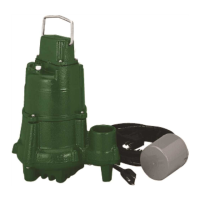
Zoeller AquaNot 508 Series Specifications

General IconGeneral
TypeSubmersible Sump Pump
Model508-0005
Horsepower1/3 HP
Voltage115 V
Motor Housing MaterialCast Iron
MaterialCast Iron
Weight22 lbs
Discharge Size1-1/2" NPT
PhaseSingle

Summary

Preinstallation Checklist

Safety Guidelines and Precautions

Electrical Safety and Handling

Covers grounding, power disconnection, qualified electricians, and battery handling.

Operational and Environmental Restrictions

Includes pump application, float switch use, indoor limits, and airlock prevention advice.

Limited Warranty

Maintenance Procedures

System Testing and Inspection

Instructions for monthly system checks, including indicator lights and alarm function.

Battery Maintenance

Guidance on adding distilled water to the battery and safety precautions.

Troubleshooting Guide

Common Issues and Solutions

Addresses frequent problems like LED alternation, pump not running, low water flow, and frequent cycling.

Alarm and Float Switch Problems

Details troubleshooting for alarm sounds, missing alarms, and float switch issues.

Product Description and Components

System Components Overview

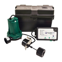
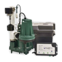
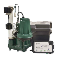
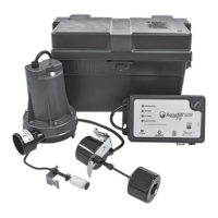
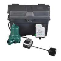
Lists and describes the parts included in the DC backup pump system.

Performance and Battery Selection

Pump Performance Data

Provides flow rate and shut-off head data for the pump at various discharge heights.

Battery Requirements

Specifies the type and capacity of 12-volt battery needed for optimal system operation.

Installation Instructions

System Setup and Piping

Guides on selecting locations, connecting piping, and installing the check valve.

Electrical Connections and Wiring

Details on connecting the charger, battery, pump, and float switch.

Float Switch Assembly

Instructions for assembling and positioning the float switch for proper operation.

Initial Start-Up and Operation

System Testing and Verification

Procedures for testing the installation for leaks and ensuring proper pump and alarm function.

Final System Check

Steps to reconnect power and verify both primary and backup pump systems are operational.

Assembly Diagrams

Submersible Pump Assembly

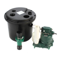
Diagram illustrating the installation of the DC pump with a submersible primary pump.

Column Pump Assembly

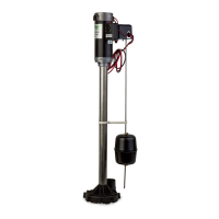
Diagram showing the installation of the DC pump with a column primary pump.

Component Views

Exploded View of DC Pump

Detailed breakdown of the DC pump and its associated electrical components.

Pump Assembly Diagram

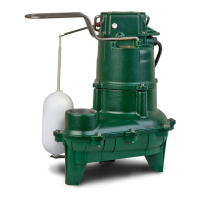
Illustrates the assembly of the pump with discharge tee and check valve.

Charger Functions and Display

Float Switch Operation

Details on float switch installation and its role in activating the pump.

Control Charger Interface

Explanation of the charger's buttons, LCD screen, and LED indicator functions.

Battery and Environmental Information

Battery Recommendations and Care

Guidelines for selecting, maintaining, and replacing the 12-volt battery.

Carbon Monoxide Detector Precautions

Advice on preventing false CO detector alarms caused by battery charging by-products.

Related product manuals