Do you have a question about the Zoeller Aquanot 508 and is the answer not in the manual?
Covers electrical safety, pump handling, and chemical warnings for safe operation and compliance.
Highlights important operational guidelines like grounding, circuit protection, and pump usage for optimal performance.
Details warranty exclusions, limitations, and legal disclaimers for product defects and liability.
Explains how purchasing an Aquanot Battery extends the limited warranty period to three years.
Guides on how to inspect and test the backup pump system for proper operation every 3 months.
Provides solutions for common problems like pump not running, low water output, or frequent cycling.
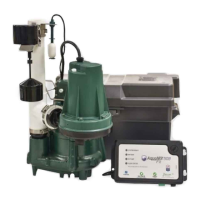
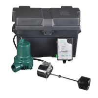
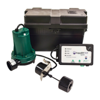
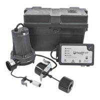
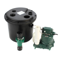
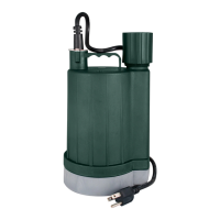
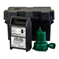
Describes the DC emergency pump as a backup for primary pumps during power outages or failures.
Details the pump's flow rate at various head pressures, including shut-off head.
Advises on choosing a suitable 12-volt deep-cycle battery for optimal backup system performance.
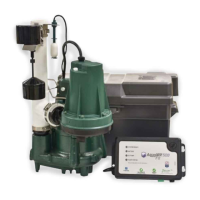
Step-by-step guide on installing the DC pump, check valve, and float switch assembly.
Instructions for connecting the control charger to the battery and pump terminals correctly.
Guides on testing the system for leaks, pump activation, alarm function, and final readiness.
Illustrates the installation of the DC pump in line with a submersible primary pump.
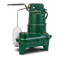
Illustrates the installation of the DC pump in line with a column primary pump.
Shows a detailed breakdown of all parts included in the DC pump system.
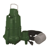
Illustrates the assembly of the pump with discharge fittings and check valve.
Details the float switch mechanism and proper installation of the locking pin.
Diagram showing connections and indicators on the control charger unit.
Explains how to navigate the LCD screen and use the buttons for system monitoring and control.
Provides guidelines for selecting and maintaining the recommended deep cycle battery for the system.
Offers advice on preventing false CO detector alarms caused by battery charging by-products.
| Model | Aquanot 508 |
|---|---|
| Category | Water Pump |
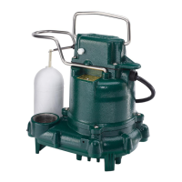
| Type | Submersible |
| Voltage | 115V |
| Max Head | 25 ft |
| Maximum Head | 25 ft |
| Discharge Size | 1-1/2 in |
| Warranty | 3 Years |
| Cord Length | 10 ft |
| Power Cord Length | 10 ft |
| Motor Housing Material | Cast Iron |
| Impeller Material | Thermoplastic |
| Material | Cast Iron |
| Horsepower | 0.5 HP |
| Phase | Single |