Do you have a question about the Zoeller AquaNot 507 Key and is the answer not in the manual?
Critical safety precautions including electrical grounding, power disconnection, and handling.
Guidelines for proper use, circuit capacity, water type, and installation environment.
Statement on the equipment's compliance with FCC rules for digital devices.
Details on warranty coverage, exclusions, and limitations for the pump system.
Manufacturer's exclusion of liability for consequential damages and implied warranties.
Explanation of the backup pump system's self-testing, diagnostics, and battery maintenance features.
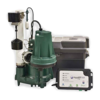
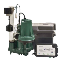
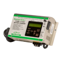
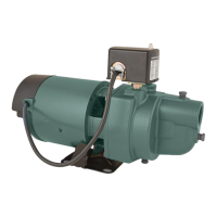
Technical details for the DC pump, controller, and battery box, including performance and construction.
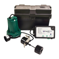
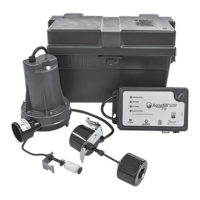
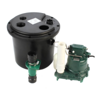
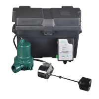
List of parts included in the installation kit for the AquaNot 507 Key system.
Flow rate specifications for the DC pump at various head pressures.
Guidelines for selecting a suitable 12-volt deep-cycle battery for optimal system performance.
Step-by-step instructions for physically installing the pump, controller, and float switch.
Steps to test the pump and controller for proper functionality and leak detection.
Instructions for silencing alarms, understanding LED indicators, and resetting the controller.
Visual representation of how the DC backup pump is installed within the sump pit system.
Labeled diagram of the Aquanot Key controller, showing buttons, LEDs, and ports.
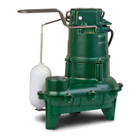
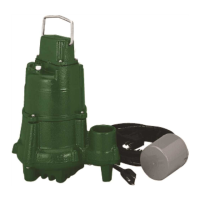
Diagrams illustrating the Aquanot Key float switch and the 507 DC pump.
Explanation of the Silence/Reset and Test buttons on the Key controller.
Table detailing the meaning of solid, flashing, and off states for controller LEDs.
Guidelines for periodic inspection and testing of the backup pump system.
Solutions for problems like pump not running, low water flow, or frequent cycling.
Advice on selecting, maintaining, and replacing batteries for the system.
Information on how charging batteries may affect carbon monoxide detectors.
The Zoeller AquaNot 507 Key™ is a 12-volt DC battery backup pump system designed to protect against basement flooding during power outages or primary sump pump failures. This system acts as a secondary defense, ensuring continuous water removal when the main pump is inoperable or without power.
The core function of the AquaNot 507 Key™ is to automatically activate and pump water out of a sump pit when the primary sump pump fails or when AC power is interrupted. The system is equipped with a sophisticated controller that features built-in smart diagnostics, allowing for self-testing and fault detection. This intelligent controller continuously monitors the system's status, including the DC pump, float switch, and battery.
One of the key features is its self-testing capability. The controller is factory programmed to self-test the pump for several seconds every 24 hours, ensuring that the pump is always ready for operation. If the DC pump is unplugged, jammed, or if the float switch is missing or unplugged, the system will trigger an alarm condition, alerting the user to a potential issue. The controller can also differentiate between the pump moving air versus pumping water, which helps in diagnosing and remedying airlock situations. This smart float logic also prevents continuous running or dry running of the pump, extending its lifespan.
The system includes a charger that maintains the battery in a ready state and recharges it after use when AC power is restored. The recharge time varies depending on the amount of power consumed during the pumping cycle. A completely drained battery may take up to three days to fully recharge. The controller is designed to optimize battery charging and maintenance, which helps to extend the battery's overall life.
The AquaNot 507 Key™ is designed for ease of use and provides clear indicators for its operational status. The controller features a "System Ready" light that glows green when the unit is plugged into a 115 V wall outlet and there are no alarm conditions. A "Battery" LED indicates the battery's condition, showing green for charged, yellow for charging, and red for low or bad battery. A "DC Pump" LED indicates when the pump is running (yellow) or if there's a pump fault (red). A "Float Status" LED indicates a float fault (red).
The system includes two primary buttons on the controller: "Silence/Reset" and "Test." The "Silence/Reset" button allows users to silence current alarms for 24 hours with a short press, or to reset the alarm and clear flashing lights by holding it for more than 3 seconds. The "Test" button initiates a pump run to determine if the amp draw is within range and starts the 24-hour timer for self-testing.
For installation, the system requires a properly grounded 115 V receptacle, and the control box and battery must be located within 6 feet (1.8 m) of the pump and basin. It is crucial not to use an extension cord for the power supply. The DC emergency pump is specifically designed for clear water and should not be used in septic tanks or for pumping sewage. The installation process involves connecting the DC pump to the primary pump's discharge line using a tee fitting and an in-line check valve. The operational float switch is installed above the "on" level of the primary pump, with careful positioning to ensure free movement and prevent interference.
Regular maintenance is essential to ensure the AquaNot 507 Key™ system operates effectively. The manual recommends inspecting and testing the system for proper operations at least every three months. For wet cell batteries, electrolyte levels should be checked monthly, though this is not required for "maintenance-free" battery types.
To test the system, users should first check that the "System Ready" light is green. Then, the primary pump and controller should be unplugged from their power supply. The sump should be filled with water until the DC pump activates, allowing it to run for a few minutes. The alarm will sound approximately one second after the pump starts, and it can be silenced by pressing the "Silence/Reset" button. After the test, the pump will shut off once the water level is lowered and the float drops to the "off" position. Finally, the controller and primary pump should be reconnected to the wall outlets. The battery light will turn yellow during charging and then green once fully charged.
The owner is responsible for checking the battery and battery connection at least once a month. Batteries contain acid, so caution must be exercised when handling them. The system's controller is designed to extend battery life through optimized charging, but batteries should be replaced every three years. It is recommended to use a B.C.I. size 27 deep-cycle battery with a 175-minute reserve capacity or larger. Users should avoid letting corrosion build up on the battery terminals and should use the included plastic battery box to keep the battery safe and clean.
In troubleshooting, the manual provides guidance for common issues such as the DC pump not running, pumping little or no water, or cycling too frequently. It advises checking connections, wire terminal points, battery charge, and the 30 amp fuse on the controller. For intermittent pumping, it suggests checking for airlocks and baffling incoming water to reduce turbulence. If the alarm sounds during the battery recharge cycle, it can be silenced by unplugging the charger and disconnecting the black lead from the battery, then checking and replacing the battery if necessary before reconnecting.
The system also addresses the potential for gaseous by-products from charging batteries to cause false activation of carbon monoxide (CO) detectors. Zoeller Pump Company recommends moving the battery as far away from the CO detector as possible or venting the battery to the exterior to prevent false alarms.
| Type | Submersible Sump Pump |
|---|---|
| Maximum Head | 25 ft |
| Discharge Size | 1-1/2 in NPT |
| Voltage | 115 V |
| Cord Length | 10 ft |
| Housing Material | Cast Iron |
| Material | Cast Iron |
| Float Switch Included | Yes |
| Horsepower | 0.3 HP |
| Switch Type | Vertical |
| Phase | Single |