7
© Copyright 2015 Zoeller
®
Co. All rights reserved.
Indoor Prepackaged System Installation Instructions
This set of instructions is for factory prepackaged indoor systems only. If your system
is a eld assembled indoor system, use these instructions as a guideline. If your system is an outdoor
system then go to the next section in this manual that covers outdoor systems.
1. Indoor grinder pump systems are for installing at
grade in an indoor application only. If you will be
installing this system outside next to the residence
then you will need an outdoor system. DO NOT
INSTALL THE INDOOR SYSTEM OUTDOORS.
2. Review the drawing in Fig. 5 on page 6 and
the actual system to become familiar with the
components in the grinder pump system. Review
where the unit will be installed. Determine where
the power feed, inlet pipe, discharge pipe and vent
will be located.
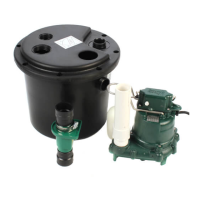
3. Remove the unit from the packing. Indoor
prepackaged systems are preassembled at the
Zoeller Company and require a minimum of eld
assembly work. All work inside the basin can be
performed via the inspection port. There should
be no reason to remove the cover from the basin.
Pump and oat switches are already set inside the
basin.
4. Remove the inspection plate from the cover. All
oats are set and tethered for proper operation from
the factory. Verify that where the oat switches are
set will work for your application. Verifying that
the oat switches are set properly and will not
hang up inside the basin is the responsibility
of the installing contractor. Float switches are
tied in place for shipping purposes. Cut the cable
tie around each oat switch bulb or the unit will
not operate properly.
5. Dig a hole for the basin. The basin should be
located in a very low trac area within 15’
(4.6 m) of the power disconnect. The hole should
be at least 8” (203 mm) larger in diameter than the
basin in order to leave 4” (102 mm) of backll all
the way around the perimeter. A minimum of 4”
(102 mm) of compacted subbase is also required.
Backll and subbase should be 1/8” (3.2 mm) to
3/4” (19 mm) pea gravel or 1/8” (3.2 mm) to 1/2”
(12.7 mm) crushed stone. Also reference the basin
installation instructions included with the unit.
6. The 4” (102 mm) inlet hub should be located
between the top lip of the basin and the alarm
oat “on” level with a minimum distance of 10”
(254 mm) between the oor of the basin and hub.
Determine the location of the inlet hub based upon
your inlet pipe arrangement. The inlet hub must
be used with 4” (102 mm) pipe. It is best to install
the inlet on the side of the basin opposite the oat
switches. Most systems are supplied with a eld
installed 4" (102 mm) pipe seal inlet tting. This
inlet tting is installed in the basin's side-wall in
a 5" (127 mm) hole drilled with a hole saw at a
location lining up with the inlet pipe.
7. Set the basin in the hole and connect the 4"
(102 mm) inlet pipe to the inlet hub using the rubber
insert. Backll around the basin with specied
media. Care should be taken not to damage
components or leave voids when backlling. Finish
grade of oor should be poured in place around
the top 6” (152 mm) of the basin assembly.
8. Connect the discharge pipe, valves and vent
according to all applicable National, State and
Local plumbing codes.
9. Mount the control panel on the wall within 15’
(4.6 m) of the system. Connect the oat switch
and pump cords.
10. Clean any debris out of the basin. Fill the basin with
water and check the system for proper operation.
11. Record system start-up data for future reference.
12. Seal and secure the inspection plate to the lid using
the proper bolts and sealant. Pouring concrete
around the system can now be completed.
 Loading...