3
© Copyright 2015 Zoeller
®
Co. All rights reserved.
Preinstallation Checklist
SEE BELOW FOR LIST OF WARNINGS
SEE BELOW FOR LIST OF CAUTIONS
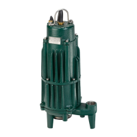
1. Inspect your grinder pump. If the unit has been damaged in
shipment, contact your dealer before installing. Do Not remove the
test plug in the cover nor the motor housing.
2. Carefully read all literature to familiarize yourself with details
regarding installation and use. Retain materials for future reference.
1. Make sure pump connection contains a ground terminal. The
power cord on all Zoeller Grinder Pumps contains a green conductor for
grounding to help protect you against the possibility of electric shock.
2. Make certain the electrical service is within reach of the power
supply cord.
3. Make sure any panels and branch circuits are equipped with
proper size fuses and circuit breakers. An independent power circuit
is recommended, sized according to the Governing Electrical Code,
for the current shown on the grinder pump nameplate.
4. For your protection, always disconnect the power source to the
grinder pump before handling. All grinder pumps must be properly
grounded and wired in accordance with the Governing Electrical Codes
and all local codes and ordinances.
5. Installation of electrical hardware and checking of control panels
and circuits should be performed by a qualied licensed electrician.
6. Risk of electrical shock - These pumps have not been investigated
for use in swimming pool areas.
7. The appliance is not intended for use by persons (including children)
with reduced physical, sensory or mental capabilities, or lack of experience
and knowledge, unless they have been given supervision or instruction to
concerning use of the appliance by a person responsible for their safety.
1. Make sure the power source is capable of handling the electrical
requirements of the grinder pump, as indicated on the nameplate.
2. A disconnect switch should be installed ahead of the pump.
3. The Grinder pumps are operated by control panels with variable level
oat control switches. It is the responsibility of the installing party to
see that oat control switches will not hang up on the grinder pump
or other pit peculiarities and are secured so that the grinder pump
will shut off. It is recommended to use rigid pipe and ttings and
the pit be 24" (610 mm) in diameter for simplex systems and 36"
(91 cm) in diameter for duplex systems or larger.
4. Grinder installations should be checked yearly for debris and/or build
up which may interfere with the “ON” or “OFF” positions of variable
level oat control switches. Repair and service, other than cutter
assembly maintenance, should be performed by Zoeller Engineered
Products authorized service stations only.
5. Maximum operating temperature must not exceed 130°F,
(54°C).
6. Pump and float switch electrical connections must be
permanently installed, operational and protected from
submergence.
7. Junction box conduit must be installed with watertight
connection. Zoeller junction boxes include a UL Listed potting
kit for sealing the conduit. Failure to properly install this sealant
material could void warranty.
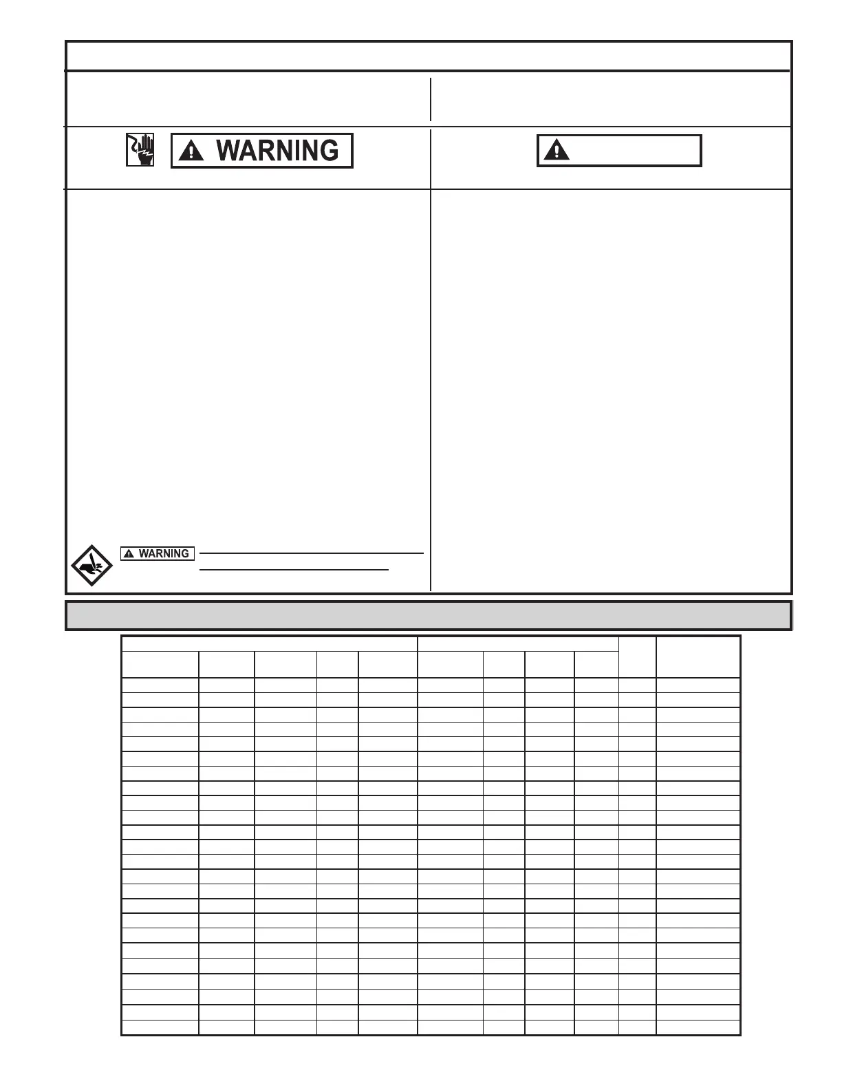
Electrical Data
Amps
KVA
Code
Winding
Resistance
Line-to-Line
Model RPM Voltage Phase Hertz Full Load In Air Shut O
Locked
Rotor
AK7011 2800 380 3 50 4.4 1.6 2.8 18 G 9.7
I7011 3450 200 1 60 20.0 6.6 12.1 60 H 1.0 / 1.5
E7011 3450 230 1 60 17.2 4.0 10.9 56 F 1.3 / 4.0
J7011 3450 200 3 60 12.3 3.7 7.7 54 L 1.9
F7011 3450 230 3 60 10.8 3.3 6.9 42 K 2.4
K7011 3450 380 3 60 6.8 3.2 4.2 28 H 4.8
G7011 3450 460 3 60 5.5 1.6 3.5 21 K 9.7
BA7011 3450 575 3 60 4.5 1.0 2.5 11 F 15.3
AK7012 2800 380 3 50 4.4 1.6 2.8 18 G 9.7
I7012 3450 200 1 60 20.0 6.6 12.1 60 H 1.0 / 1.5
E7012 3450 230 1 60 17.2 4.0 10.9 56 F 1.3 / 4.0
J7012 3450 200 3 60 12.3 3.7 7.7 54 L 1.9
F7012 3450 230 3 60 10.8 3.3 6.9 42 K 2.4
K7012 3450 380 3 60 6.8 3.2 4.2 28 H 4.8
G7012 3450 460 3 60 5.5 1.6 3.5 21 K 9.7
BA7012 3450 575 3 60 4.5 1.0 2.5 11 F 15.3
AK7013 2800 380 3 50 4.4 1.6 2.8 18 G 9.7
I7013 3450 200 1 60 20.0 6.6 12.1 60 H 1.0 / 1.5
E7013 3450 230 1 60 17.2 4.0 10.9 56 F 1.3 / 4.0
J7013 3450 200 2 60 12.3 3.7 7.7 54 L 1.9
F7013 3450 230 2 60 10.8 3.3 6.9 42 K 2.4
K7013 3450 380 3 60 6.8 3.2 4.2 28 H 4.8
G7013 3450 460 2 60 5.5 1.6 3.5 21 K 9.7
BA7013 3450 575 2 60 4.5 1.0 2.5 11 F 15.3
Do not attempt to turn star cutter located
on bottom of the unit with ngers. Use a
wrench when checking or removing star cutter.
 Loading...