QWIK JON
®
ULTIMA 202 SYSTEM
INSTALLATION INSTRUCTIONS
PREINSTALLATION CHECKLIST
NOTICE TO INSTALLER: Instructions must remain with installation.
SECTION: W2.50.025
FM2369_Ec
0214
Supersedes
1213
1. Inspect all materials. Occasionally, products are damaged during shipment. If the unit is damaged, contact your dealer before using. DO NOT remove the
test plugs from the pump.
2. Carefullyreadalltheliteratureprovidedtofamiliarizeyourselfwithspecicdetailsregardinginstallationanduse.Thesematerialsshouldberetainedfor
future reference.
SEE BELOW FOR LIST OF NOTES
REFER TO WARRANTY ON PAGE 2.
SEE BELOW FOR LIST OF WARNINGS
SEE BELOW FOR LIST OF CAUTIONS
Patent No. 7,203,976
Other Patents Pending
Product information presented
here reects conditions at time
of publication. Consult factory
regarding discrepancies or
inconsistencies.
MAIL TO: P.O. BOX 16347 • Louisville, KY 40256-0347 USA
SHIP TO: 3649 Cane Run Road • Louisville, KY 40211-1961 USA
+1 (502) 778-2731 • FAX +1 (502) 774-3624
®
Your Peace of Mind is Our Top Priority
®
visit our web site:
www.zoeller.com
50/60Hz
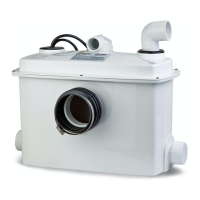
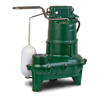
1. TheQwikJon
®
Ultimais ttedwitha specially-designedgrinderpump
and is capable of pumping fecal matter, toilet paper and sanitary articles
which may be accidentally dropped into the toilet. It is not recommended
toushsuchforeignobjectsastheymightclogthesanitarysewer.
2. Checktobesureyourpowersourceisadequatetohandletheamperage
requirementsofthemotorasindicatedonthepumporunitI.D.tag.
3. All plumbing (discharge and vent lines) must be installed to meet governing
codes. Unit must be vented. Do not use an automatic plumbing
vent device.
4. Maximum operating temperature must not exceed 54°C (130°F).
5. Donotusecleaningproductscontainingbleachinthetoilettank,toiletor
attachedxturesastheywilldegradethepumpseals.
1. Repair and service should be performed by an Authorized Service Station
only (consult factory).
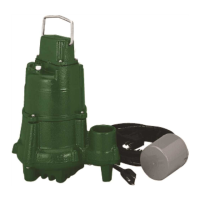
2. Recommended for installations with total dynamic head up to 6 m (20') for
60 Hz or 5 m (15') for 50 Hz. Consult factory if 50 Hz installation is above
5m(15')verticalheightinDN25(1")pipeorif60Hzinstallationisabove
4m(13')verticalheight.Mini-GrinderPumpisdesignedforuseinQwik
Jon
®
Ultima units only. It is not designed for use in any other application.
3. Pumpswiththe“UL”markand/orthe“US”markaretested to ULStandard
UL778.CSACertiedpumpsare certiedtoCSAStandardC22.2No.
108.QwikJon
®
Ultima units only. It is not designed for use in any other
application.
4. Model202toiletutilizes4.8or6.1liters(1.28or1.6gallons)perush.
5. Allxturesconnectingtothesystemmustbeonthesameoorlevel.
1. Toreducetheriskofelectricalshock,aproperlygroundedreceptacleor
controlboxmustbeinstalledinaccordancewiththegoverningcodes.Never
remove ground pin from plug.
2.Makecertainthatthegroundfaultinterrupterprotectedreceptacleorcontrol
boxiswithinthereachofthepump’spowersupplycord.DONOTUSEAN
EXTENSIONCORD.Extensioncordsthataretoolongortoolight donot
deliversufcientvoltagetothepumpmotor,andtheycouldpresentasafety
hazard if the insulation were to become damaged or the connection end were
to fall into a damp or wet area.
3.Makesurethepump'selectricalsupplycircuitisequippedwithfusesorcircuit
breakersofpropercapacity.Aseparatebranchcircuitisrecommended,sized
according to the governing electrical codes for the current shown on the pump
name plate.
4. Testing for ground. As a safety measure, each electrical outlet should be
checkedforgroundusinganUnderwritersLaboratoryListedcircuitanalyzer
which will indicate if the power, neutral and ground wires are correctly connected
toyouroutlet.Iftheyarenot,callaqualiedlicensedelectrician.
5. FORYOUR PROTECTION,ALWAYS DISCONNECTPUMP FROMITS
POWERSOURCEBEFOREHANDLING.Ifpumpiswireddirect,de-energize
thecircuitatthecontrolbox.DONOT,UNDERANYCIRCUMSTANCES,
REMOVETHEGROUNDPIN.Wearinsulatedprotectiveshoesanddonot
standinwater.Certainplugtypesmayincludea3-pronggroundplugtohelp
protectagainstelectricalshock.Aproperlygrounded3-prongreceptacleor
control box must be installed in accordance with governing codes.
6. Installation and servicing of the pump's electrical circuits and hardware should
onlybeperformedbyaqualiedlicensedelectrician.
7. Installation andmaintenanceof thisapplianceisnot intendedforpersons
(including children) with reduced physical, sensory or mental capabilities, or
lackofexperienceorknowledge,unlesstheyhavebeengivensupervisionor
instruction concerning use of the appliance by a person responsible for their
safety.
8. Risk of electrical shock.Donotremovepowersupplycordandstrainrelief
or connect conduit directly to the pump. If the supply cable is damaged, it
must be replaced by an authorized Zoeller Representative.
9. Pumpcontainsoilwhichbecomespressurizedandhotwhenoperating.Allow
2½ hours after disconnecting before attempting service.
10. Pumpisnotintendedforpotablewaterduetopossiblecontaminationbyoil
contained in the pump.
11. Risk of electric shock.Thesepumpshavenotbeeninvestigatedforusein
swimming pools and marine areas.
DATE INSTALLED:
MODEL NUMBER:
© Copyright 2014 Zoeller Co. All rights reserved.