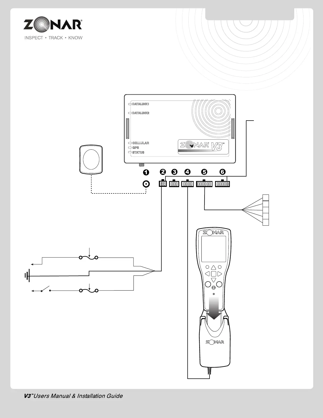
Constant Power Supply
Input Voltage: 8-30VDC
Engine Running: 8-30 VDC
Acc/Accessory mode, Engine Not Running: 0 VDC
+12VDC (Red)
Optional
2010 Handheld Reader
Part#: 20046 (Marigold)
Zonar V3™
Part#: 10079
Optional
GPS Messaging Vehicle Mount
Part#: 80312
Cable Length: 8 ft.
3A-5A
12 Pin Data I/O Cable
Part#: 80059
Cable length: 18 in.
Fig. 23-1
Light Duty
MOAC-T
MOAC-B
Cable Length: 118”
1. External GPS antenna (Optional)
2. 4 Pin Power Input
3. 6 Pin Accessory
- ZPass
- Virtual Trainer
4. 8 Pin 2010 Vehicle Mount (Optional)
5. 12 Pin Discrete I/O (Optional)
6. 10 Pin J3 input (JBus 1708/1939 & OBDII Equipped Vehicles)
SYSTEM INSTALLATION
23
3A-5A
External GPS Antenna
(Optional)
Part#: 10006
Cable Length: 16.5 ft.
Switched
Power (White)
GND (Black)
1 Input 1
2 Input 2
3 Input 3
4 Input 4
5 Input 5
4 Pin Power Cable
Part#: 10007
Cable Length: 20 ft.
• Used on Non-JBus installs
• Used on JBus installs with JBus
switched Power Issues (as indicated by
flashing “Status” LED with engine
running)