77 / 184
Valve clearance adjustment
1. Maintenance information
1.1 General information
a. This chapter introduces the operation method of
valve clearance adjustment.
b. The adjustment of the valve clearance can only be
carried out after the engine is removed from the vehicle.
c. Adjust the valve clearance when the engine is at
room temperature (≤35℃).
1.2 Assemble torque value
No. Name Torque
N·m
1
M6×30Hexagon flange bolts
(environmentally friendly color
zinc)
10±2N.m
2
M5×15-5#Hexagon socket
head bolt (oxidized black)
5±1N.m
3
M30×1.5Aluminum screw plug
(dark gray)
16±2N.m
4
M14×1.5Screw plug
(environmental color zinc)
10±2N.m
1.3 Tools, measuring tools, accessories
a. 8# and 14# T-shaped socket wrenches, 5# and 10#
hexagon wrenches, magnet sticks, tweezers, rags;
b. Feeler gauge;
c. Thread fastening glue and sealing silica gel.
2. Operation steps
a. Use an 8# T-shaped socket wrench (or a wind
batch) to remove the 6 M6×30 hexagonal flange bolts of
the cylinder head cover, and then remove the cylinder
head cover assembly.
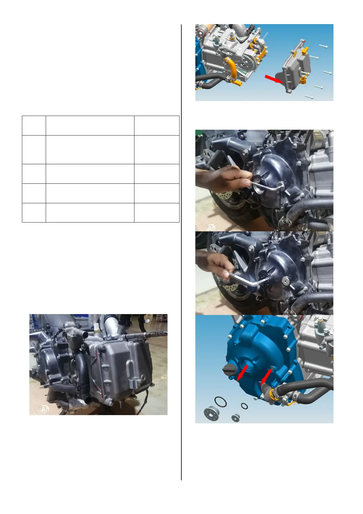
b. Use 5# and 10# Allen wrenches to remove
M14×1.5 screw plugs and M30×1.5 aluminum screw
plugs, and remove the O-ring.
c. Insert the 14#T-shaped socket wrench from the
M30×1.5 aluminum screw plug hole and set it on the
hexagonal head of the flywheel bolt, and then turn the
crankshaft clockwise to align the T-point engraved line
on the flywheel with the mark of the M14×1.5 screw plug
hole gap. At the same time, the top dead center

 Loading...