expandability. Targeting the above expandability problem, Martini draft suggests creating
a fixed number of MPLS LSPs between PE and network devices. When VC bearer
services between user CE device and PE need to pass through the network, they will
enter the point-to-point sub-tunnel (i.e. “pseudo-wire”) in MPLS LSP. This LSP can be
regarded as the bearer channel of multiple VCs. This is similar to the relation between VC
channel and VP channel in ATM network. IETF draft defines the signaling to create
sub-tunnel and the encapsulation format of forwarding ATM, FR and Ethernet data
packets on sub-tunnel. Although this method save some network resource (such as LSP
quantity), but when creating large-scale MPLS VPN, we need create all sub-tunnels
manually; the configuration workload is quite high.
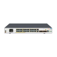
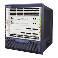
ZXR10 8900E series products support VPWS of Martini draft and extended LDP protocol.
They can create different LSP channels by service type. They support Ethernet
encapsulation and VLAN encapsulation as well as LDP-based extended VPLS.
3.3.3.1 VPLS
Virtual Private LAN Service (VPLS) is a kind of VPN with multi-station link in a single
bridge domain in IP/MPLS network managed by operators. All customer stations in VPLS
seem to locate in one LAN no matter where they actually locate. Since VPLS uses
Ethernet interface to implement customer exchange, it simplifies LAN/WAN boundary
and makes service providing quick and flexible. In VPLS, customers keep the complete
control over routing. Besides, since all routers of customers in VPLS are a part of the
same sub-net (LAN), they get a simplified IP address solution. This advantage becomes
especially obvious when it is compared with the full-meshed structure constituted by
different P2P links. Operators can also get benefits by reducing the complexity of VPLS
service management.
In Figure 3-7, CE1, CE2, and CE3 are in one VPLS domain – VPLS A. They are
connected by a packet switching network (here is MPLS network). Equipped with VPLS,
PEs establish Full-Meshed VC connection between each other. If CE1 communicates
with CE3, CE1 first learns MAC address of CE3, which is based on data flow. Meanwhile,
there must be two layers of tags to PE3 on PE1. One is packet switching tag for outer
layer, which is MPLS network here, and the other is VC tag for the inner layer. When PE1
receives MAC frames with the destination address of CE3, PE searches for inner and
outer layer tags arriving PE3 according to MAC address, VCID and other information, and
adds the tags to the data frames and transport them through MPLS network. Only inner
layer tags are left with the data when it arrives PE3. PE3 gets the connecting port of PE3
where CE3 locates according to inner layer tag and MAC address, and transport it from
the port. The data will arrive CE3. In this way communication between CE1 and CE3 is
completed. Here all operations are implemented based on L2. Operators don’t need to
concern users’ routing configuration so that it reduces users dependence on operators,
and simplifies operators’ management of user services.
 Loading...
