EasyManua.ls Logo

ZURN EZ1 User Manual

ZURN EZ1
6 pages
To Next Page IconTo Next Page
Page #1 background imageLoading...
Page #1 background image
EZ1
TM
DRAINAGE SERIES
EZ1
TM
FLOOR DRAIN INSTALLATION INSTRUCTIONS
Zurn Industries, LLC | Specification Drainage Operation
1801 Pittsburgh Avenue, Erie, PA U.S.A. 16502 · Ph. 855-663-9876, Fax 814-454-7929
In Canada | Zurn Industries Limited
3544 Nashua Drive, Mississauga, Ontario L4V 1L2 · Ph. 905-405-8272, Fax 905-405-1292
www.zur n.com
Rev. C
Date: 02/27/2018
C.N. No. 139680
Form No. FD97
Page 1 of 6
®
Fig. 1
1. Cut pipe so that the height of the finished drain is at or just
below the height of the finished floor. (See Zurn Engineering
Handbook or EZ1
TM
Submittal for dimensional heights). Ensure
pipe is cut square and free of burrs or debris. See Fig. 1
2. Install drain body on pipe and pressure test connection per local
code requirements. See Fig. 2 (Neo-loc body shown for
reference)
Note: All plastic bodies to be solvent welded to pipe
3. Pour the rough floor slab flush with the top of the drain body.
See Fig. 3
Fig. 2
Fig. 3
Warning: Flying material can cause eye injury or blindness and sharp edges could cause cuts or
lacerations. Wear safety glasses and gloves when installing or working on drain.
WARNING: Cancer and Reproductive Harm - www.P65Warnings.ca.gov
ADVERTENCIA: Cáncer y daño reproductivo - www.P65Warnings.ca.gov
AVERTISSEMENT: Cancer et effets néfastes sur la reproduction - www.P65Warnings.ca.gov
Question and Answer IconNeed help?

Do you have a question about the ZURN EZ1 and is the answer not in the manual?

ZURN EZ1 Specifications

General IconGeneral
BrandZURN
ModelEZ1
CategoryPlumbing Product
LanguageEnglish

Summary

EZ1 TM FLOOR DRAIN INSTALLATION INSTRUCTIONS

General Safety Warning

Warning: Wear safety glasses and gloves due to flying material and sharp edges.

Cut Pipe to Height

Cut pipe to match finished floor height, ensuring it's square and free of debris.

Install Drain Body and Test

Install drain body and pressure test connection per local code requirements.

Pour Rough Floor Slab

Pour the rough floor slab flush with the top of the drain body.

Install Waterproofing Membrane

Install waterproofing membrane and secure clamp collar with screw, minding torque limits.

Install Rough-in Cover Assembly

Install rough-in cover and adjust to finish floor grade, preventing concrete seepage.

Pour Finish Floor Slab

Pour finish floor slab flush with the top of the rough-in cover.

Loosen Rough-in Cover Bond

Hit rough-in cover top with pliers to create a crack around circumference, loosening bond.

Expose Slot in Rough-in Cover

Break the protective label in the center to expose a slot for removal.

Remove Rough-in Cover

Unscrew the rough-in cover counterclockwise using pliers in the exposed slot.

Remove Rough-in Cover (Continued)

Remove the rough-in cover; keep it for potential adjustments for tilted drains.

Slab On Grade Installation

Round Slab Installation

Apply silicone, thread head assembly flush, apply silicone to strainer frame, turn clockwise.

Square Slab Installation

Turn head assembly clockwise, then fill shroud with cement/grout flush with finished floor.

Tile Installation

Round Tile Installation

Adjust head assembly to finished floor height, then install finish flooring.

Square Tile Installation

Adjust head assembly, fill shroud with cement/grout, then install finish flooring.

Correcting a Tilted Drain

Remove Strainer and Frame

Remove the strainer and strainer frame from the installed head assembly for adjustments.

Adjust with Shims and Screws

Use shims and longer screws to level the strainer with the floor, then reinstall.
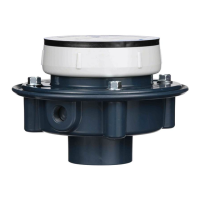
Related product manuals