Tip
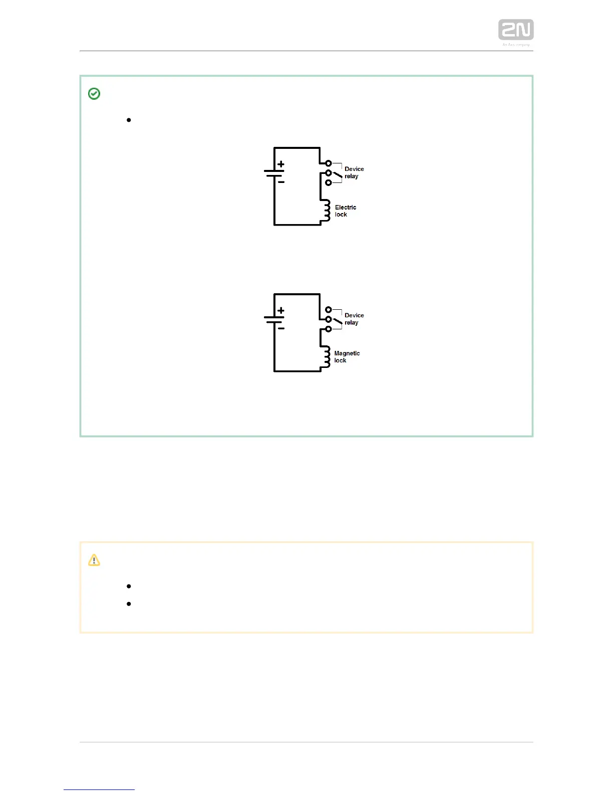
Output wiring diagram for Relay terminals
The electric lock is opened by power supply connection.
The magnetic lock is opened by power supply disconnection.
LAN Connection
2N IP Force
®
is connected to the LAN via a RJ-45 terminated (connector X11) UTP
/STP cable (of category Cat 5e or higher). The system is equipped with the Auto-
MDIX function and so both the straight and crossed cable versions can be used.
Caution
We recommend the use of a LAN surge protection.
We recommend the use of a shielded SSTP Ethernet cable.
External Power Supply Connection
2N IP Force
®
can be fed either from an external 12 V ±15 % / 2 A DC power supply or
from the LAN equipped with the PoE 802.3af supporting network elements.