1.
2.
3.
4.
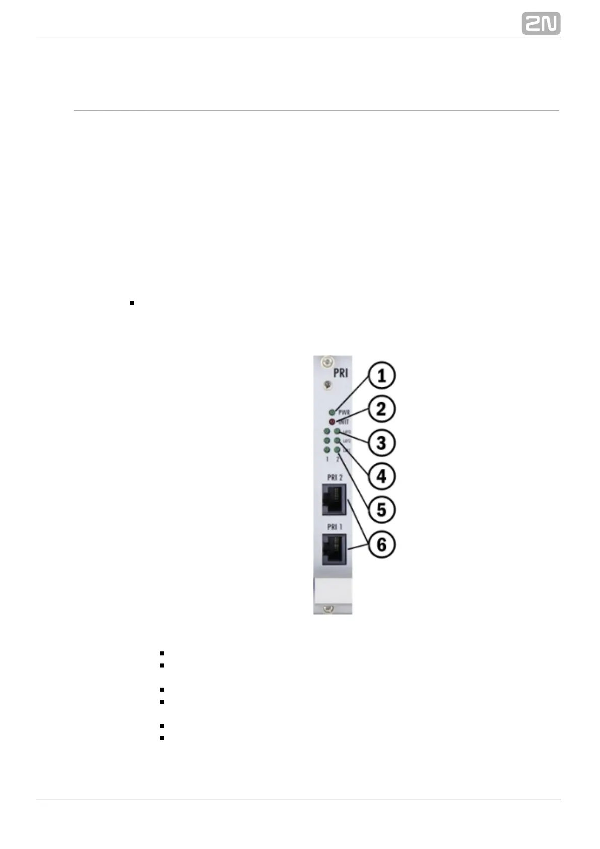
PRI Board
Board Description
The PRI board contains one or two (depends on the part number) ISDN interfaces and
PCM bus timing circuits. PRI 1 is designed as an internal interface (with an activated
LCR function) and PRI 2 as an external interface (all calls from the port are always
routed to PRI 1). The interface can work in the MASTER or SLAVE mode (set the PRI 1
mode using the web interface and PRI 2 has always the opposite mode). The output
can be configured as TERMINAL (TE) or NETWORK (NT) by jumpers (switching of wires
– for software switch you have to use the web interface!). The settings of these
jumpers HAVE TO match the PRI configuration – two NT and TE modes will cause
malfunction of the PRI board or back-up connection* ! The board is designed on a
4-layer PCB of the size of 160x100mm. There are also 5 (or 8 in 2ISDN PRI) board
status indicators, which are located on the front panel.
The PRI board contains four switches (can be deactivated by jumpers), which
provide hardware connection between PRI 1 and PRI 2 in case the system is
switched off or inoperative.
Board supply indication
Shining: Switched on
Flashing: Board in the sleep mode
Board supply indication
Shining: Switched on
Flashing: Board in the sleep mode
Status of ISDN layer 3 on PRI 1/2 interfaces
Shining: One or more calls are connected over selected interface
Flashing: B-channel in restartLight off: No active call
Status of ISDN layer 2 on PRI 1 (2) interfaces: