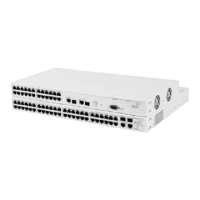
Switch 4400 — Front View Detail 17
the appropriate connection. Alternatively, you can manually set these
ports to 10BASE-T half duplex, 10BASE-T full duplex, 100BASE-TX half
duplex or 100BASE-TX full duplex. The maximum segment length is
100 m (328 ft) over Category 5 twisted pair cable.
The 4400 PWR will supply up to 15.4W of power through any of the 24
front panel ports in conformance to the 802.3af specification. The Switch
4400 PWR incorporates a LED Mode Button on the front panel, which
when pressed changes the mode of the front panel port LEDs
functionality between Switch and Power mode.
LEDs Tab l e 4
lists LEDs visible on the front of the Switch, and how to read their
status according to color. For information on using the LEDs for problem
solving, see “Solving Problems Indicated by LEDs”
on page 56.
Table 4 LED behavior
LED Color Indicates
Port LEDs
Packet Green Full duplex packets are being transmitted/received on the
port.
Yellow Half duplex packets are being transmitted/received on the
port.
Off No packets are being transmitted/received on the port.
Status Green A high speed (100 Mbps) link is present, and the port is
enabled.
Green flashing A high speed (100 Mbps) link is present, but the port is
disabled.
Yellow A low speed (10 Mbps) link is present, and the port is
enabled.
Yellow flashing A low speed (10 Mbps) link is present, but the port is
disabled.
Yellow flashing
(fast)
The port has failed and has been automatically disabled. The
Switch passes its Power On Self Test and continues to
operate normally even if one or more ports are disabled.
Off No link is present.
Port LEDs — PoE mode (3C17205 only)
Packet Green Power is being delivered to the port.
Green flashing Exceeded port power limit (overCurrent MIB state) or unable
to supply power due to unit over budget (denyLowPriority
MIB state).
Yellow PoE error, no power supplied on port.
DUA1720-3AAA05.book Page 17 Friday, March 7, 2003 11:53 AM