62 CHAPTER 5: INSTALLING OR REMOVING AN INTERFACE MODULE
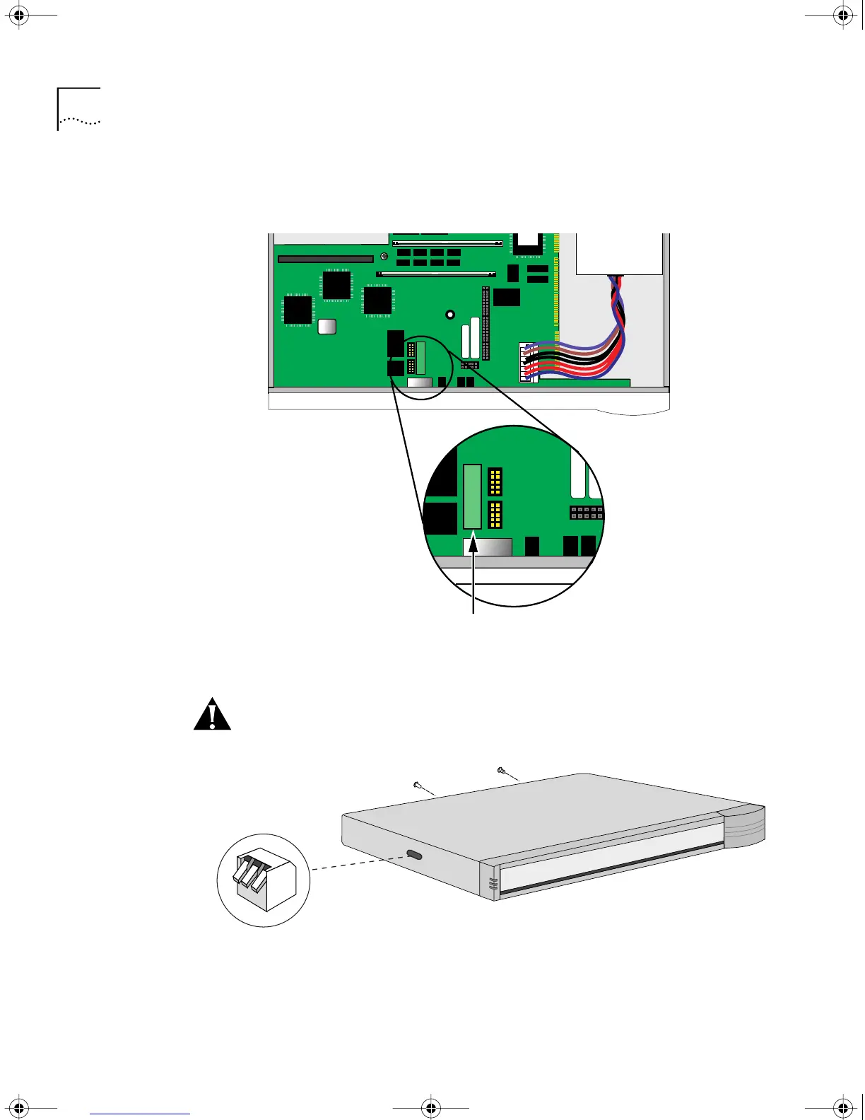
3 If you are not installing another module, change the jumper to the
left-hand set of pins and reinstall the screw on the standoff.
4 Reinstall the cover and the cover screws.
CAUTION: The DIP switches should all be in the down position. The DIP
switches are accessible through an opening on the side of the chassis.
5 If the bridge/router was mounted with brackets, reinstall the brackets and
remount it.
6 Reconnect the power cord and all cables.
Front panel
Move the jumper to the
left-hand set of pins
DIP switches should all
be in the down position
Install screws
HWBook Page 62 Friday, June 19, 1998 3:42 PM