Page 14 of 39 RTE6701-OEM Integration Manual VC27U V1.03 DRAFT.doc
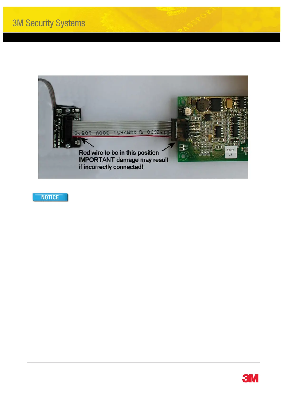
Connect the 10 way read head cable to the read head and then to J2 of the VC27U as follows:
The read head will be damaged if the connector is reversed or misaligned.
The read head is marked with a red dot to indicate the pin 1 end of the header.
Connect the 3 wire cable from the read head to J4 of the VC27U. Note this connector only fits one way, with
the small lugs facing away from the PCB. The red wire must go to pin 1 of J4.
Connect the USB Interface Cable to J3 of the VC27U PCB. Note this connector only fits one way, with the
small lugs facing away from the PCB.
Connect the host connector of the USB Interface Cable to the PC and then install the drivers using the New
Hardware Found Wizard as described in section 3.4.
You should now be able to determine the COM port number as shown in section 3.5.
Check which protocol you have installed, usually this would be RTE Native unless you have ordered an
alternative protocol. Test the module using a test program described in section 5 below.
By default the serial port is set to 19200 baud, 7 data bits, even parity and 1 stop bit. This may be changed
using the jumper block J6 depending on the protocol installed.
 Loading...