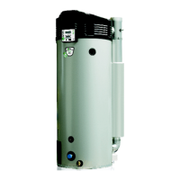
3 Interface
3.1 Operator interface
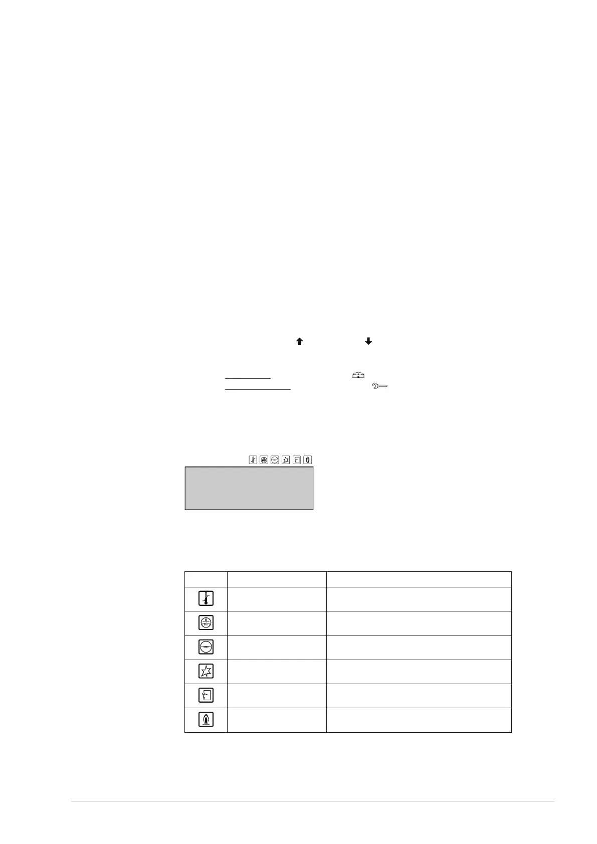
The operator interface is completely menu-driven, and comprises:
a 4-line display with 20 characters per line;
6 buttons for controlling the water heater (below the display);
6 graphical symbols (above the display);
a connector for a service PC;
a control switch.
The buttons are divided into three groups:
Navigation buttons:
Buttons for UP [
], and DOWN [ ];
Enter: [ENTER].
Reset button: [RESET].
The main menu (see section 4.3): [ ];
The service program (see section 9.2): [ ].
This chapter is specifically intended for the service and maintenance engineer and
installation engineer.
In this manual, the display of the operator interface is shown as in the figure, both with
and without icons.
3.2 Explanation of icons
The table explains the meanings of the icons.
Name Explanation
Heat demand Heat demand detected
Purge Pre- and post-purge using fan
Pressure switch Pressure switch is closed
Glow (Pre)glow
Gas control valve Gas control valve open/ignition
Flame detection Water heater operational
•
•
•
•
•
•
-
-
-
•
•
0311704_BFC_28-120_III_ENEN_V2.4, 2022-10-17 19