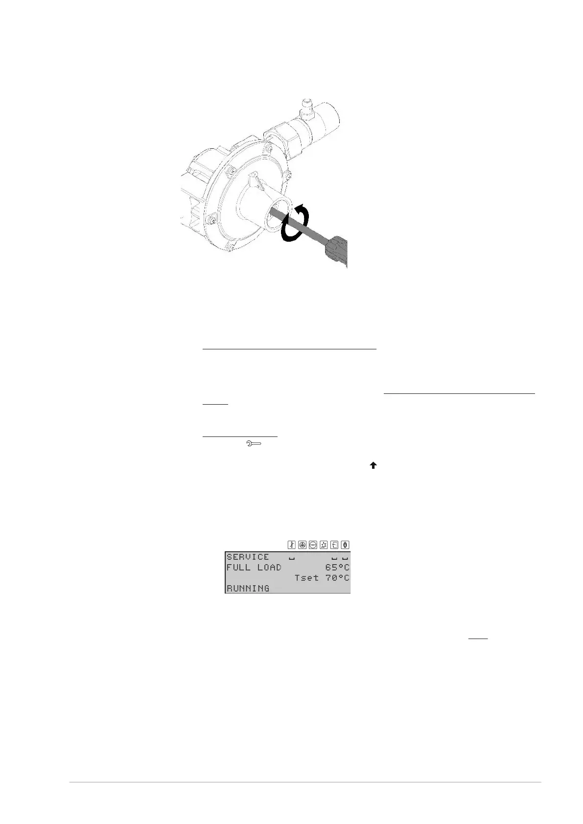
Fig. Gas control valve pressure adjustment
7.8.4 CO
2
adjustment
To check the CO
2
value under full load and partial load and to adjust it if necessary,
proceed as follows:
Isolate the appliance from the power supply (see section 4.2.2).
Carefully remove the covers from the appliance.
The electrical section is now visible.
Place the CO
2
meter's measurement probe in the test nipple (58) of the flue gas
outlet pipe (the number is a reference on the
General working principle of the water
heater (see section 5.1)).
Open the gas supply and vent the gas supply line.
Use the main switch to apply mains voltage to the appliance.
Start the appliance (see section 4.1).
Go to the [ ] SERVICE OPERATION menu.
Generate a heat demand by draining the appliance until it is cold or by raising the
value for T
set
in the SERVICE menu. Use [
] for this.
Full load measurement
From the service menu, select:
SERVICE OPERATION | FULL LOAD
Confirm with [ENTER].
The appliance is now in FULL LOAD mode and will ignite.
The appliance is now running at FULL LOAD. Read the value from the CO
2
meter
and wait until this measured value has remained stable for some time. This may take
several minutes.
Then compare the measured CO
2
value against the value from the
table (see section
12.3).
The CO
2
value at full load must be within ±1.0 vol% of the CO
2
value stated in the
table.
1.
2.
3.
4.
5.
6.
7.
8.
9.
10.
-
-
11.
12.
0311704_BFC_28-120_III_ENEN_V2.4, 2022-10-17 71