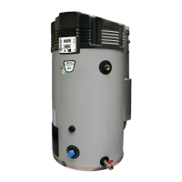
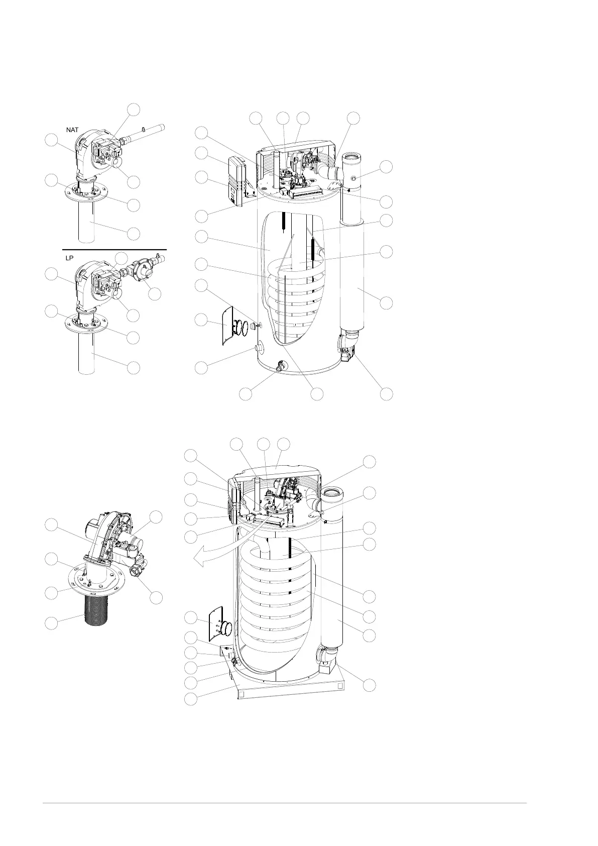
Fig. Water heater BFC 28, 30, 50, 60
12 5
7
4
6
28
10
11
13
12
14
15 24 23
22
8
9
3
58
19
16
18
20
30
21
17
18
20
17
21
30
59
16
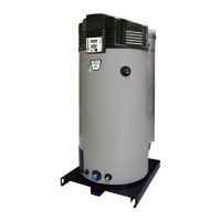
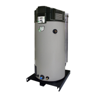
Fig. Water heater BFC 80, 100, 120
12 5
7
4
6
28
10
11
13
12
14
15
24
23
22
8
9
3
58
19
29
16
18
20
30
21
17
1. Cover
2. Hot water outlet
3. Electrical connector block
4. Controller
5. Pressure switch
6. Control panel
7. Temperature sensor T
1
8. Combustion chamber
9. Anode
10. Tank
11. Heat exchanger
12. Inspection and cleaning
opening
13. Temperature sensor T
2
14. Cold water inlet
15. Drain valve
16. Gas control valve
17. Burner
18. Fan
19. Air supply hose
20. Hot surface igniter
21. Flame probe
22. Chimney pipe
23. Condens trap
24. Insulation layer
28. Potentiostat
29. Base
30. Venturi
58. Flue gas test point
59. Pressure-reducing valve
44 Installation, Maintenance and Service part