10
GAS SUPPLY SYSTEMS
Low pressure building gas supply systems are dened as those
systemsthatcannotunderanycircumstancesexceed14”W.C.
(1/2PSIGauge).Thesesystemsdonotrequirepressureregulation.
Measurementsshouldbetakentoinsurethatgaspressuresarestable
andfallwithintherequirementsstatedonthewaterheaterratingplate.
readingsshould be takenwith all gas burning equipment off (static
pressure)andwithallgasburningequipmentrunningatmaximumrate
(dynamicpressure).Thegassupplypressuremustbestablewithin1.5”
W.C.fromstatictodynamicpressuretoprovidegoodperformance.
Pressuredropsthatexceed1.5”W.C.maycauseroughstarting,noisy
combustionornuisanceoutages.Increasesorspikesinstaticpressure
duringoffcyclesmaycausefailuretoigniteorinseverecasesdamage
toappliancegasvalves.Ifyourlowpressuresystemdoesnotmeet
theserequirements,theinstallerisresponsibleforthecorrections.
HighPressurebuildingsupplysystemsusepressuresthatexceed
14” W.C. (1/2 PSI Gauge).These systems must use eld supplied
regulatorstolowerthegaspressuretolessthan14”W.C.(1/2PSI
Gauge).Appliancesrequiregasregulatorsthatareproperlysizedforthe
waterheaterinputanddelivertheratingplatespeciedpressures.Gas
supplysystemswherepressureexceeds5PSIoftenrequiremultiple
regulatorstoachievedesiredpressures.Systemsinexcessof5PSI
buildingpressureshouldbedesignedbygasdeliveryprofessionals
forbestperformance.Waterheatersconnectedtogassupplysystems
thatexceed14”W.C.(1/2PSIGauge)atanytimemustbeequipped
withagassupplyregulator.
GAS PRESSURE REQUIREMENTS
BL-100naturalgasmodelrequiresaminimumgassupplypressureof
5”w.c.(1.25kPa);BL-80naturalgasmodelrequiresaminimumgas
supplypressureof6”w.c.(1.49kPa).Theminimumsupplypressure
is measured while gas is owing (dynamic pressure). The supply
pressure(dynamic)shouldneverfallbelowthespeciedminimum
supplypressure.Thesupplypressureshouldbemeasuredwithallgas
redappliancesconnectedtothecommonmainringatfullcapacity.If
thesupplypressuredropsmorethan1.5”W.C.(0.37kPa)asgasbegins
toowtothewaterheaterthenthesupplygassystemincludingthe
gaslineand/orthegasregulatormayberestrictedorundersized.See
SupplyGasregulatorsectionandGasPipingsectionofthismanual.
Thegasvalveonallmodelshasamaximumgassupplypressurelimit
of14”W.C.(3.48kPa)Themaximumsupplypressureismeasured
whilegasisnotowing(staticpressure).
SUPPLY GAS REGULATOR
Themaximumallowablegassupplypressureforthiswaterheater
is14.0inchesW.C.(3.48kPa).Installapositivelock-upgaspressure
regulatorinthegassupplylineifinletgaspressurecanexceed14.0
inchesW.C.(3.48kPa)atany time. regulators mustbesized/used
accordingtomanufacturer’sspecications.
Ifapositivelock-upregulatorisrequiredfollowtheseinstructions:
1. Positivelock-upgaspressureregulatorsmustberatedatorabove
theinputBtu/hrratingofthewaterheatertheysupply.
2. Positivelock-upgaspressureregulator(s)shouldbeinstalledno
closerthan3feet(1meter)andnofartherthan8feet(2.4meters)
ofequivalentlengthfromthewaterheater’sinletgasconnection.
3. Afterinstallingthepositivelock-upgaspressureregulator(s)aninitial
nominalsupplypressuresettingof7.0”W.C.whilethewaterheater
isoperatingisrecommendedandwillgenerallyprovidegood
waterheateroperation.Someadditionaladjustmentmayberequired
latertomaintainasteadygassupplypressure.
4. When installing multiple water heaters in the same gas supply
system it is recommended that individual positive lock-up gas
pressureregulatorsbeinstalledateachunit.
MIXING VALVES
Water temperature over 125°F (52°C)
can cause severe burns instantly
resulting in severe injury or death.
Children, the elderly and the physically
or mentally disabled are at highest risk
for scald injury.
Feel water before bathing or showering.
Temperature limiting devices such as
mixing valves must be installed when
required by codes and to ensure safe
temperatures at fixtures.
Waterheatedtoatemperaturewhichwillsatisfyclotheswashing,dish
washing,andothersanitizingneedscanscaldandcausepermanent
injuryuponcontact.Shortrepeatedheatingcyclescausedbysmall
hotwaterusescancausetemperaturesatthepointofusetoexceed
thewaterheater’stemperaturesettingbyupto20°F(11°C).
Somepeoplearemorelikelytobepermanentlyinjuredbyhotwater
than others. These include the elderly, children, the inrm and the
physically/mentally disabled.Table 2 shows the approximate time-
to-burnrelationshipfornormaladultskin.Ifanyoneusinghotwater
provided by the water heater being installed ts into one of these
groupsorifthereisalocalcodeorstatelawrequiringacertainwater
temperatureatthepointofuse,thenspecialprecautionsmustbetaken.
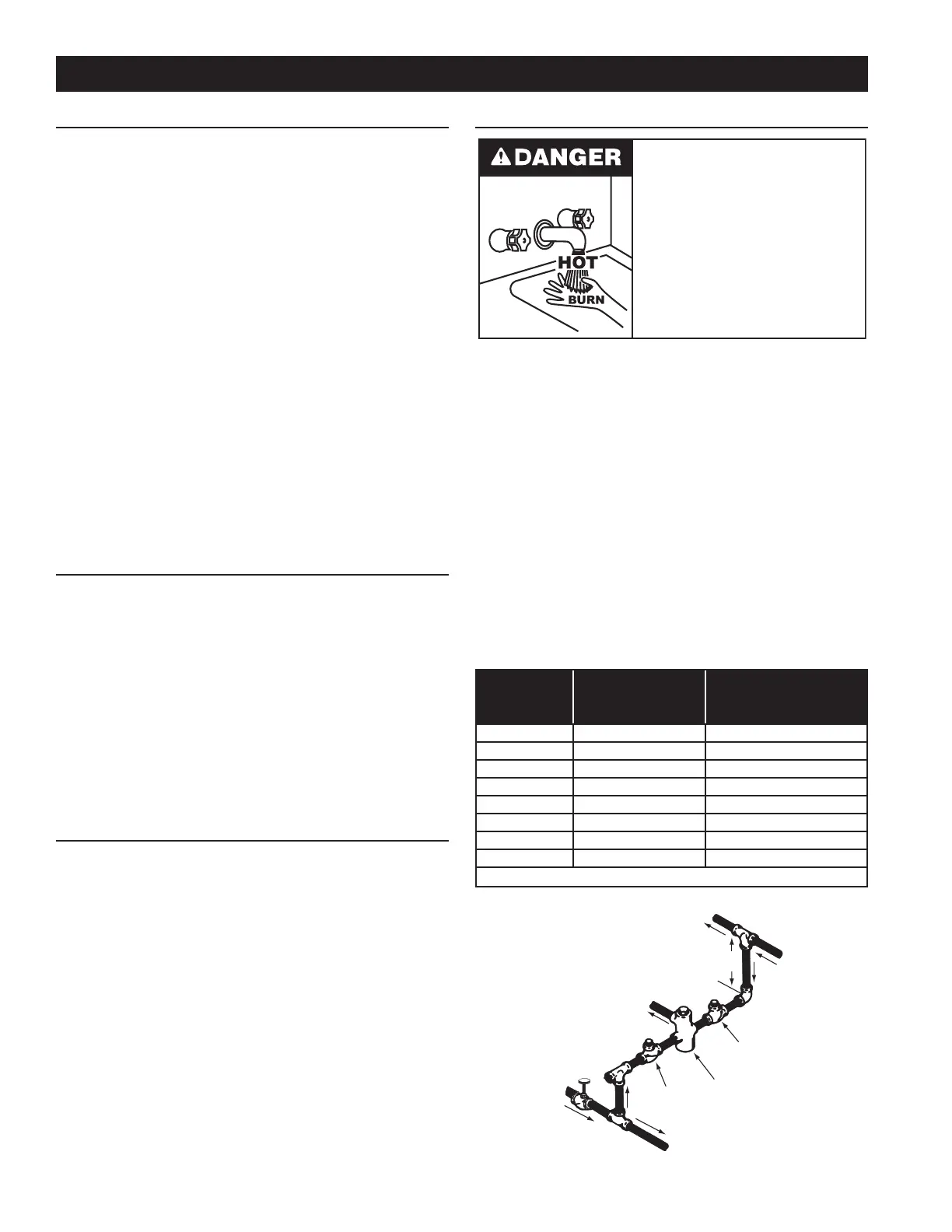
In addition to using the lowest possible temperature setting that
satisesdemandoftheapplicationaMixingValveshouldbeinstalled
atthewaterheaterorathotwatertapstofurtherreducesystemwater
temperature.SeeFigure6.
Mixing valves are available at plumbing supply stores. Consult
a Qualied Installer or Service Technician. Follow mixing valve
manufacturer’sinstructionsforinstallationofthevalves.
TABLE 2.
Water
Temperature°F
Timefor
1stDegreeBurn
(LessSevereBurns)
TimeforPermanentBurns
2nd&3rdDegree
(MostSevereBurns)
110
(normalshowertemp.)
116 (painthreshold)
116 35minutes 45minutes
122 1minute 5minutes
131 5seconds 25seconds
140 2seconds 5seconds
149 1second 2seconds
154 instantaneous 1second
(U.S.GovernmentMemorandum,C.P.S.C.,PeterL.Armstrong,Sept.15,1978)
OUTLET
TO TANK
CHECK
VALVE
MIXING
VALVE
COLD
WATER
INLET
TEMPERED WATER
OUTLET
12” TO 15”
(30-38 cm)
CHECK
VALVE
FIGURE 6.
INSTALLATION REQUIREMENTS
 Loading...