26 100299634_2000545244_ Rev. A
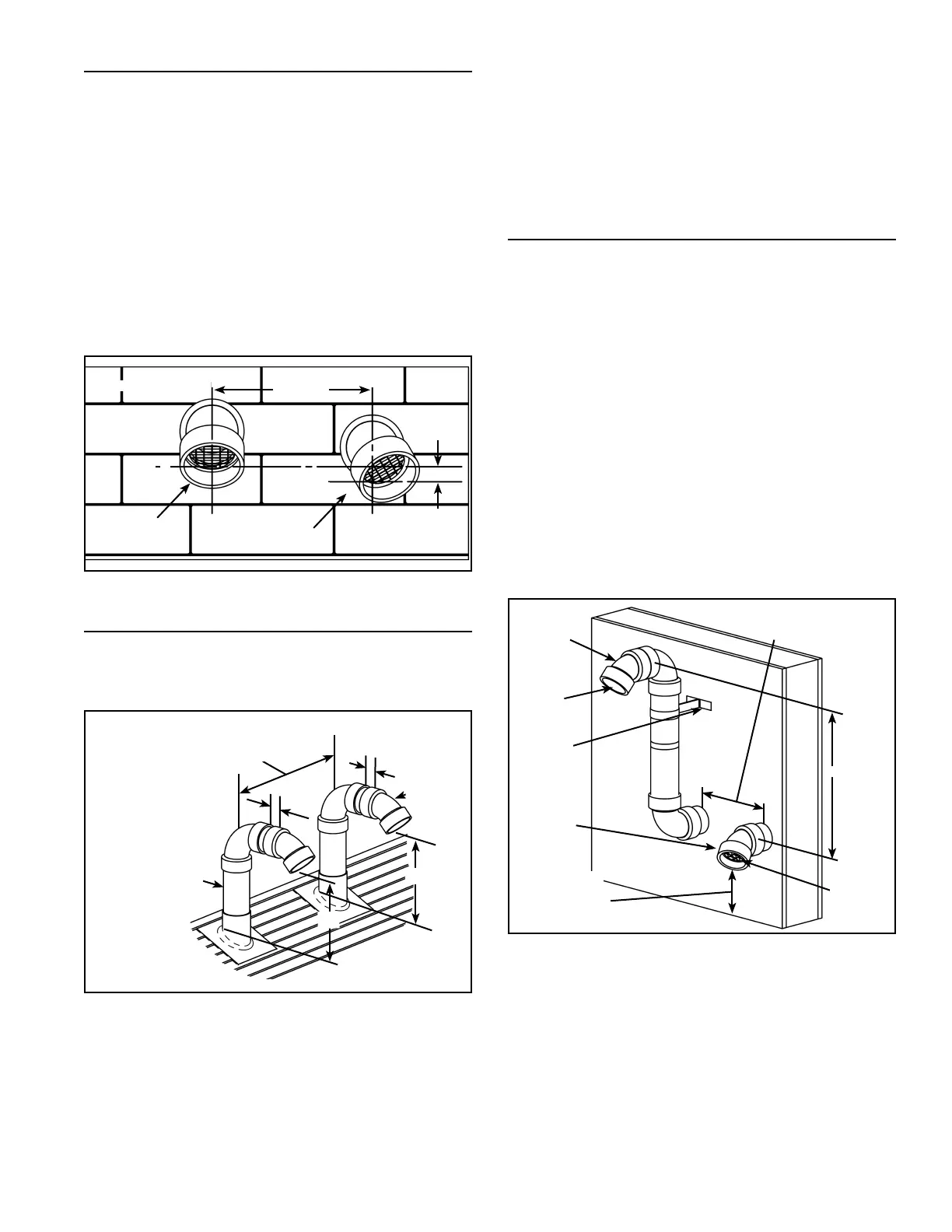
SIDE WALL VENT TERMINATION (STANDARD)
Important: When terminating the vent on a side wall, the
following specifications pertaining to terminal location must
be followed (see Figure 21).
1. The air intake terminal and the exhaust vent terminal
must terminate on the same exterior wall.
2. The vertical centerline of the air intake terminal
must be located at a minimum of 8” from the vertical
centerline of the exhaust vent terminal.
3. The horizontal centerline of the air intake terminal may
not be located more than 24” below the horizontal
centerline of the exhaust vent terminal.
4. To avoid exhaust recirculation, the air intake terminal
may be rotated away from the exhaust vent terminal
(see Figure 21).
EXHAUST
VENT
TERMINAL
INTAKE
VENT
TERMINAL
24” MAX
8” MIN.
L
C
L
C
L
C
L
C
SIDE WALL
Figure 21.
ROOF VENT TERMINATION (STANDARD)
Important: When terminating the vents through a roof,
the following specifications pertaining to terminal location
must be followed (see Figure 22).
A
B
1”
EXHAUST
VENT
TERMINAL
INTAKE
VENT
TERMINAL
8” MIN.
1”
“A” & “B”:12” ABOVE
ANTICIPATED SNOW
LEVEL OR 12” MIN.
ABOVE ROOF.
Figure 22.
1. The air intake termination and the exhaust vent
termination shall extend 12” above anticipated snow
level and at least 12” above the roof.
2. Must provide proper support for all pipes protruding
through roof.
3. The vertical roof terminations should be sealed with a
plumbing roof boot or equivalent flashing.
4. The air intake termination and the exhaust vent
termination must penetrate the same side of roof.
5. The centerline of the air intake termination and the
centerline of the exhaust vent termination must not
be closer than 8” .
6. The air intake terminal and the exhaust vent terminal
must be oriented facing downward and the same
direction.
SIDE WALL VENT FOR COLD CLIMATES
Some winter weather conditions present a risk of ice
accumulation at the intake termination screen. Such
accumulation will restrict intake air flow. If local conditions
present this risk, the termination configuration shown in
Figure 23 is recommended. This will reduce the possibility
of exhaust gas recirculation as well as reduce the chance
of ice accumulation.
If necessary to avoid snow accumulation, the intake vent
terminal may be fitted with a riser similar to that on the
exhaust vent terminal. Both the intake and exhaust vent
terminations may be 90° elbows if specified by local
requirements.
Note: The vertical centerline of the air intake termination
and the vertical centerline of the exhaust vent termination
must not be closer than 8” .
Important: Elbows (excluding the termination elbow) and
risers must be considered when calculating total equivalent
vent length (see Table 4).
WALL
MOUNTED
SUPPORT
BRACKET
8” MIN.
24” MAX.
INTAKE
TERMINAL
EXHAUST
TERMINAL
VENT
SCREEN
INSIDE
12” ABOVE
GRADE OR
12”ABOVE
ANTICIPATED
SNOW LEVEL
VENT
SCREEN
Figure 23.
Debris screens may be removed while there is a risk of ice
accumulation but this can make the air intake susceptible
to debris buildup, the entry of birds, other small animals or
rodents. If the debris screens are removed to prevent ice
accumulation, it is recommended that they be re-installed
when the risk of ice accumulation has passed.
 Loading...