A. O. Smith Water Products Company Service Handbook
Irving, Texas 2000
©
Training Department
17
NORMAL INDICATIONS / READINGS
AFTER TANK IS SATISFIED
Tank temperature above control setting
• On/off switch is “on”
Normal conditions will be 120 volts present to ground and:
• Each black terminal of on/off switch
• CN 1 black term 1
• CN 4 black term 1
Note: CN 6 black term 2 (flame sensor) may display 90-100 VAC – this is a non-reading, ignore it
24 VAC present to ground and:
• CN 3 red term 1 and red term 4
• CN 4 blue term 4
• CN 6 brown term 4
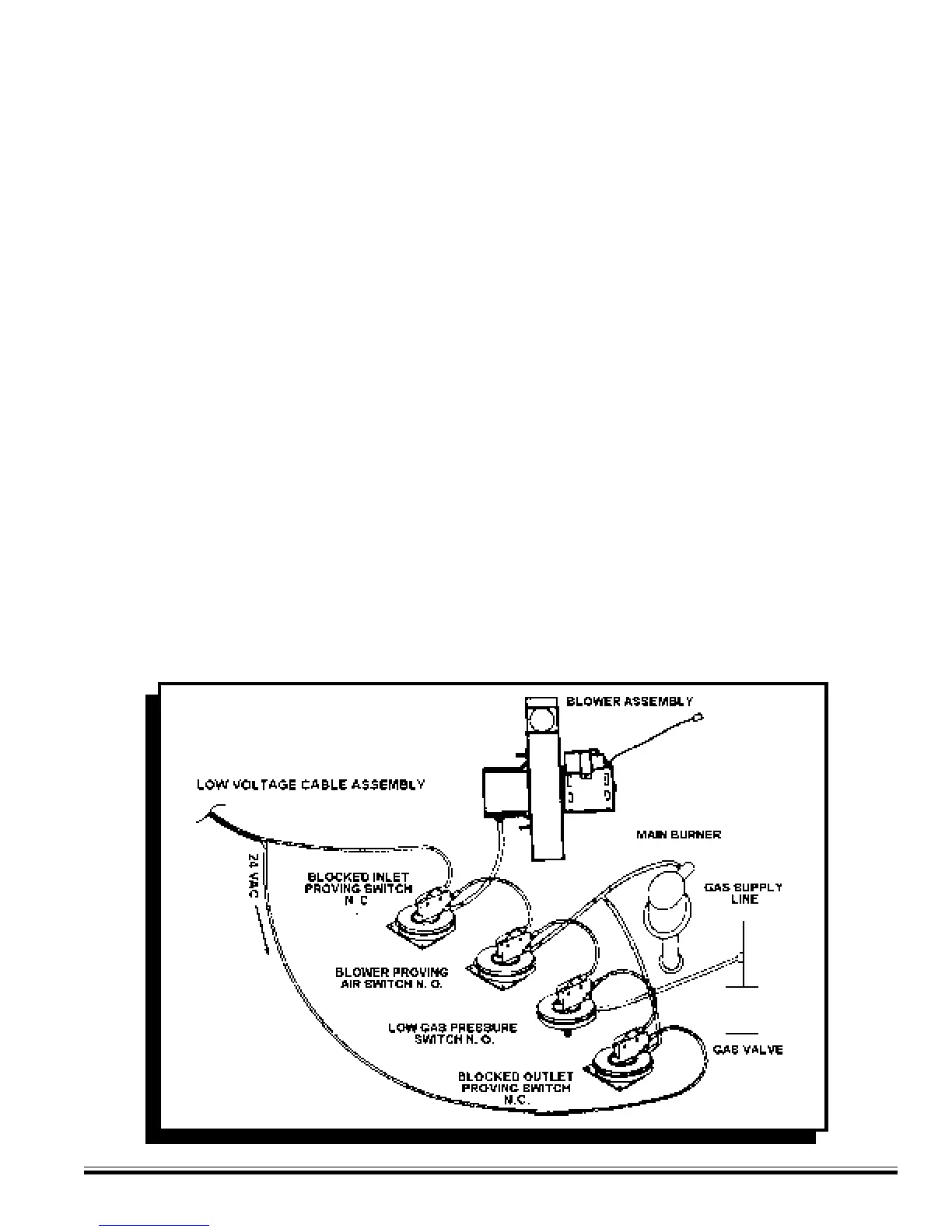
• Blocked inlet switch – each terminal (tube connects to inlet of blower)
• Blower prover switch – upper terminal (this is the jumper wire from the blocked inlet switch)
Control panel indication light “on”
• On/off switch light
• 120 VAC
• 24 VAC
• High limit
• Control status
• Current (average) tank temperature will be displayed
(BTH 120, 250 Only)