A. O. Smith Water Products Company Service Handbook
Irving, Texas 2000©
Training Department
26
TROUBLESHOOTING
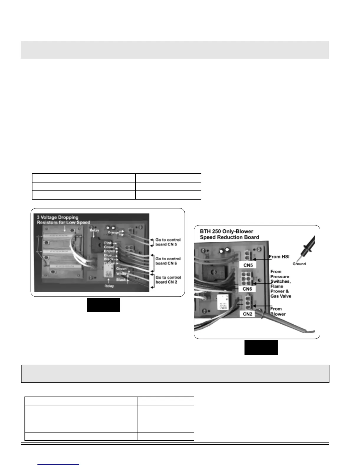
STEP 9A - BLOWER SPEED REDUCTION TEST
STEP 9B - BLOWER TEST
BTH 250 ONLY
HAS BLOWER SPEED REDUCTION BOARD
Blower wires (CN 2), igniter wires (CN 5), gas valve pressure switches and flame sense (CN6) plug directly
into blower speed reduction board.
The cables from the blower speed reduction board plug into the control board recepticles CN 2, CN 5, and
CN 6.
• 120 VAC present at CN 2 term 1 to gnd.
• Blower not running
• Tank is calling for heat
STEP 9A. Check for 120 VAC from blower speed reduction board plug (CN 2) term 1 (black wire) to
ground.
IF… THEN
120 VAC is not present replace the blower s
120 VAC is present replace the blower
STEP 9B.
STEP 9A
STEP 9B
120 Volts on meter
IF … THEN
blower operates OK go to Step 10.
blower runs but does not reduce
speed during igniter warm up or stops
during igniter warm up
replace blower spe
*
*Voltage from blower at low speed
will be approximately 80 VAC.