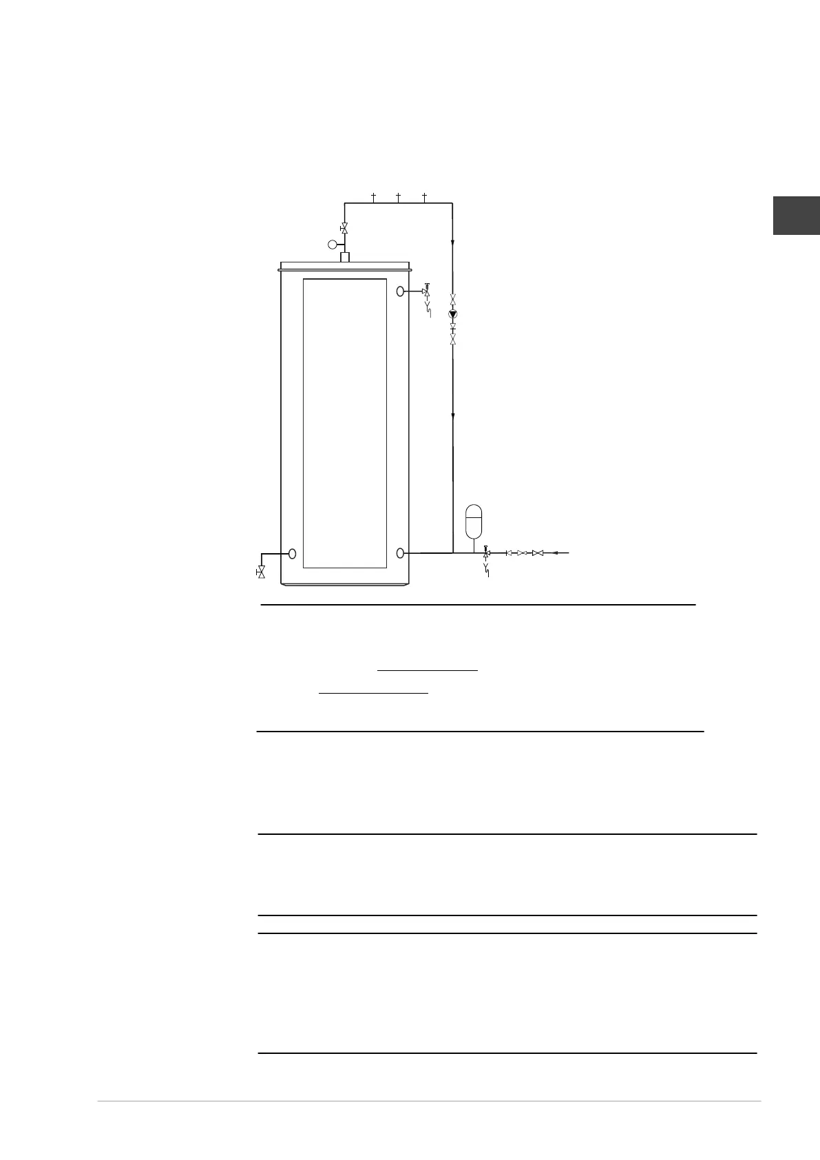
8.3 Installation diagram
Fig. Installation diagram
T
B
12
A
4
5
C
1
15
16
4
5
6
4
14
1414
11
9
3
1. Pressure reducing valve
(mandatory if the mains water
pressure is too high)
3. T&P valve (mandatory)
4. Stop valve (recommended)
5. Non-return valve
6. Circulation pump (optional)
9. Drain valve
11. Service stop valve
12. Temperature gauge (optional)
14. Draw-off point
15. Expansion valve
16. Expansion vessel
A. Cold water supply
B. Hot water outlet
C. Circulation pipe
Note
Use this installation diagram when y
ou:
- install the water connections (see 8.4)
- fill the water heater (see 8.6.1)
- dr
ain the water heater
n
8.4 Water connections
8.4.1 Cold water connection
Caution
When installing the heater, y
ou need an expansion valve. The expansion valve and
associated fittings are not included in the package. The expansion valve must be suitable
for a water pressure level of up to 800 kPa. Install the expansion vessel and expansion
valve as close as possible to the water heater.
Warning
Never install a stop v
alve or a non-return valve between the expansion vessel/expansion
valve and the water heater.
Warning
The heater is intended to be connected to the water mains permanently
. Do not use a
hose set to connect the heater.
c
w
0313851_DRE_NLUKFR, 30-03-2022 37
EN