MAINTENANCE
Residen al Hybrid Electric Heat Pump Water Heater Use and Care Guide • 31
• A replacement ECO (available by
calling the number in the “REPAIR
PARTS LIST” on page 33). A busi-
ness card to check the gap between
the ECO and tank.
• Tape and a permanent marker to
mark the wires
• A flat blade and a Phillips screw-
driver
Steps for Replacing the
ECO:
1
Turn the power OFF at the
circuit breaker or remove
fuses.
NOTICE: It is not necessary to drain the
tank to replace an ECO.
2
Open the electrical junc on box
the side of the water heater.
Using a non-contact circuit
tester, check the power wires to make
certain the power is OFF.
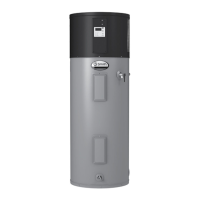
Junction Box
Power Supply
Connector
Black Wire
Red Wire
Green
Ground
Wire
1/2” Conduit
Opening
Green Ground Screw
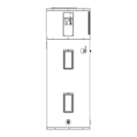
Figure 43 - Non-Contact Circuit Tester
3
Remove the upper access
panel on the water heater and
carefully fold back the
insula on and plas c element/ECO
cover (see Figure 40).
4
Make sure the replacement
ECO matches the original ECO.
5
Mark the wires with tape so
you’ll know how to put them
back on.
6
Disconnect the wires from the
bad ECO and remove the ECO
from the metal moun ng clip.
7
Install the new ECO in the
metal moun ng clip.
8
Make sure the new ECO fi ts
snuggly against the tank. You
should NOT be able to slip a
business card between the ECO and
the tank. If you can, bend the ECO
moun ng clip un l the ECO fi ts ghtly
against the tank.
9
A ach the wires following the
wiring diagram on the water
heater’s label. Make sure all
wire connec ons are ght.
10
Replace the plas c element/
ECO cover, insula on, and
access panel.
11
Replace the cover on the
electrical junc on box.
12
Restore power to the water
heater. It may take two hours
for the tank to heat up.
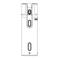
Figure 44 - Element Access Panel/ECO
Compartment
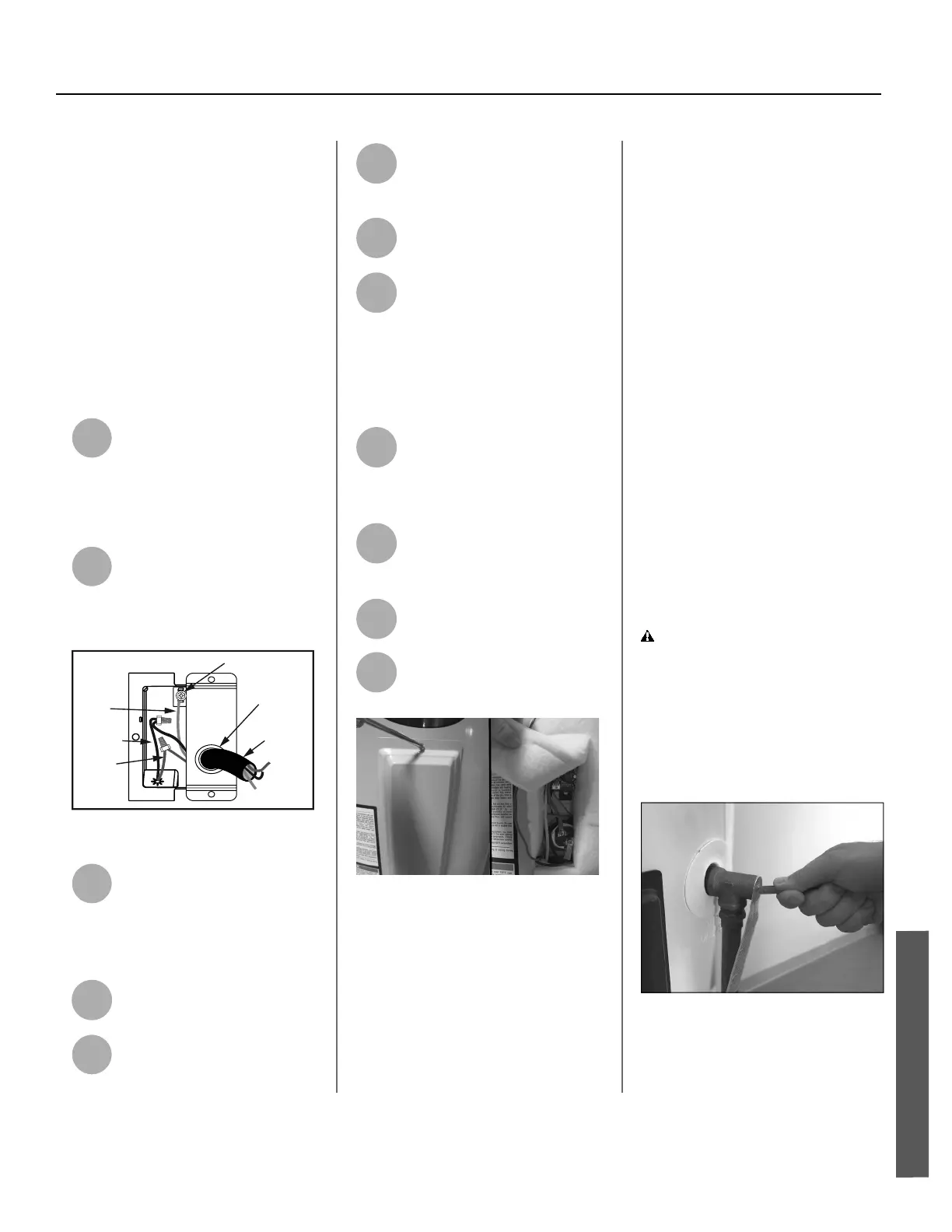
T&P Relief Valve Main-
tenance
Read and follow the opera ng and
annual maintenance instruc ons
provided by the manufacturer of the
T&P Relief Valve (yellow label a ached
to T&P Relief Valve). Minerals in the
water can form deposits that cause
the valve to s ck or create blocked
passages, making the T&P Relief Valve
inopera ve. Follow these guidelines:
• At least annually, operate the T&P
Relief Valve manually to ensure the
waterways are clear and the valve
mechanism moves freely (above).
Before operating the valve manu-
ally, check that it will discharge in a
place for secure disposal. If water
does not flow freely from the end
of the discharge pipe, turn OFF the
power to the water heater. Call a
qualified person to determine the
cause.
WARNING! Hot water will be
released. Before opera ng the T&P
relief valve manually, check that it
will discharge in a safe place. If water
does not fl ow freely from the end of
the discharge pipe, turn the power to
the water heater OFF. Call a qualifi ed
person to determine the cause.
Figure 45 - T&P Relief Valve
• At least every five years, have a
qualified person inspect the T&P
Relief Valve and discharge pipe.
MAINTENANCE
 Loading...