Do you have a question about the AAON Airflow and is the answer not in the manual?
Explains how the AAON Airflow Signal Processor receives, processes, and outputs differential pressure signals.
Lists technical details including power, accuracy, and output options for the airflow processor.
Covers essential safety precautions for electrical connections and handling static electricity.
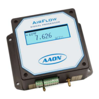
Explains the initial display shown upon powering on the device.
Details the information displayed during normal operation and specific conditions.
Provides a detailed breakdown of the purpose and operation of each key on the device.
Explains how to access and configure technical settings like network communication.
Procedure to set the unique device address for BACnet networks.
Procedure to set the instance number for BACnet communication.
Procedure to set the unique device address for Modbus networks.
Procedure to set the network communication baud rate.
Guides users to configure operational parameters like alarms and flow correction.
Details on configuring high and low alarm thresholds and delays.
Instructions on how to enable or disable individual alarms.
Procedure to set the specific flow values that trigger alarms.
Instructions for setting the time delay before an alarm is activated.
Methods for adjusting flow readings to match calibration or desired accuracy.
Setting the K-Factor to correct constant errors in flow measurements.
Using the built-in calculator to determine the K-Factor.
Procedure for restoring the device to its original factory settings.
How to review and reconfigure technical settings.
Details on the Area Factor used for converting pressure to flow.
Setting the job site altitude for air density calculations.
Procedure to set the Modbus ID for communication.
Procedure to set the network communication baud rate.
Guides users to configure operational parameters.
Setting the flow rate value representing 100% output.
Selecting units for flow rate display and values.
Correcting flow signal for air density based on temperature.
Selecting units for temperature (°F or °C).
Setting min/max temperature range for compensation.
Selecting the source for temperature input (Fixed, Variable, Network).
Entering a specific temperature value for calculations.
Configuration for device input and output signal types.
Configuring the process output signal (e.g., 4-20mA, 0-10VDC).
Configuring the temperature input signal (e.g., 4-20mA, 0-10VDC).
| Brand | AAON |
|---|---|
| Model | Airflow |
| Category | Computer Hardware |
| Language | English |