11
4. ACTIVE DISPLAYS & KEY FUNCTIONS
4.1. POWER-UP INITIATION DISPLAY
Upon initial power-up, Software Revision information will be displayed on the graphic display for
approximately 5 seconds.
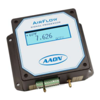
4.2. PROCESS DISPLAY DESCRIPTIONS
After power-up initialization, the following information will appear on the graphic display depending
upon the options purchased.
Flow Monitoring with an Auto
Zero Cycle
Flow Monitoring with a
High Alarm Condition
Flow Monitoring with a
Low Alarm Condition
Air Flow temperature units in degree F or C
Flashing Asterisk indicates the CPU is functioning
Displayed during an AutoZero cycle
Indicating High Alarm Value has been exceeded (High/Low Alarm Option)
Indicating Low Alarm Value has been exceeded (High/Low Alarm Option)