Zone
Zone
Two Condenser Head Pressure II Module Technical Guide
5
Zone
Zone
INSTALLATION & WIRING
Mounting and Wiring Considerations
Environmental Requirements
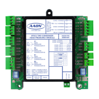
The Two Condenser Head Pressure II Module needs to be
installed in an environment that can maintain a temperature
range between -30°F and 150°F and not exceed 90% RH levels
(non-condensing).
Mounting
The Two Condenser Head Pressure II Module is housed in a
plastic enclosure. It is designed to be mounted by using the 3
mounting holes in the enclosure base. It is important to mount
the module in a location that is free from extreme high or low
temperatures, moisture, dust, and dirt. Be careful not to damage
the electronic components when mounting the module.
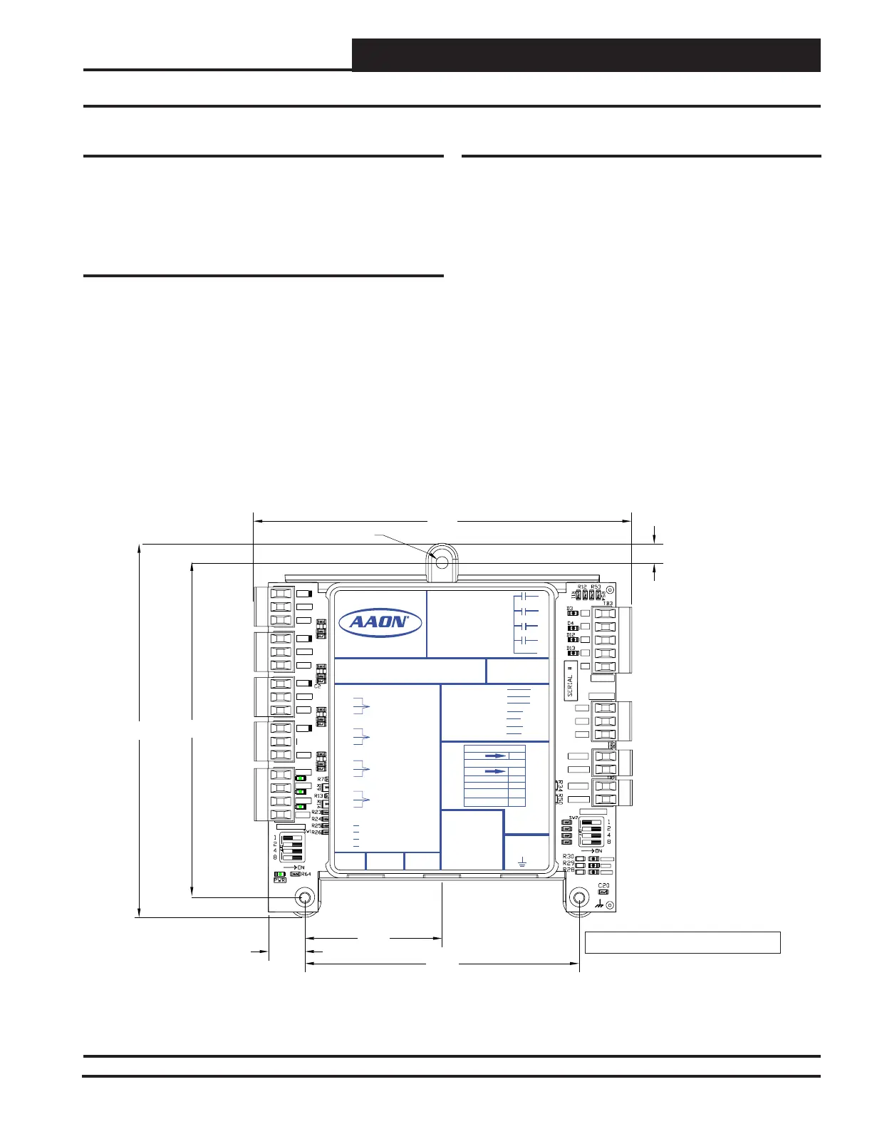
See Figure 2 for Module dimensions (in inches).
Figure 2: Two Condenser Head Pressure II Module Dimensions
Important Wiring Considerations
Please read carefully and apply the following information when
wiring the Two Condenser Head Pressure II Module:
1. To operate the Two Condenser Head Pressure II Module, you
must connect power to the 24 VAC input terminal block.
2. Each Pressure Transducer must have its own 18-gauge
shielded twisted pair cable. The Drain Wire must be the “Gnd”
signal for the transducer.
3. When the Analog Output is being used to control the
Condenser Fan Speed or Water Valve Percentage, the cable
must be 18-gauge shielded wire, and the Drain Wire must be
the “Gnd” signal.
4. If the Pulse Width Modulation (PWM) Output is being used to
directly control the ECM 142 motor, the wires do not need to
be shielded and can be any 18-gauge wire.
5.045.64
5.71
2.07
0.55
4.14
0.29
0.18 DIA. TYP.
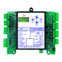
ALARM
ANALOG
STAT
COMM
R1
R2
GND
RELAYS
R3
R4
Rc
AO1
AO2
PWM1-
PWM1+
PWM2-
PWM2+
ADDRESS
OPTIONS
+5V
SIG 2
GND
+5V
SIG 3
GND
+5V
SIG 4
GND
+5V
SIG 1
GND
BIN 1
BIN 2
BIN 3
COM
LABEL P/N:
G040380
E-BUS
SIG 1
GND
+5V
SIG 2
+5V
GND
+5V
SIG 3
GND
SIG 4
GND
+5V
+24 VAC
GND
BIN 1
BIN 2
BIN 3
COM
HEAD
PRESSURE
TRANSDUCER #1
HEAD
PRESSURE
TRANSDUCER #2
HEAD
PRESSURE
TRANSDUCER #3
HEAD
PRESSURE
TRANSDUCER #4
REV. VLV. ENABLE INPUT
PWM2+
ASM01891
AAON P/N:
AO2
GND
AO1
COND. A ENABLE INPUT
COND. B ENABLE INPUT
COND. A SIGNAL
COND. B SIGNAL
PWM1-
PWM1+
PWM2-
COND. FAN A
COND. FAN B
COND. FAN A
COND. FAN B
GND
HEAD PRESSURE II MODULE
HP2C2 TWO CONDENSER
www.aaon.com
RELAY CONTACT
RATING IS 1 AMP
MAX @ 24 VAC
COND. A ENABLE
COND. B ENABLE
REV. VLV. A ENABLE
REV. VLV. B ENABLE
R1
R2
R3
R4
RC
RELAY COMMON
A1
A2
B1
B2
E-BUS
LED BLINK CODES
LED NAME
BLINKS QTY. OF SENSORS INSTALLED
LED NAME
STAT
ALARM
NO PROBLEMS
NO SENSORS DETECTED
HIGH HEAD PRESSURE
DETECTED
LOW HEAD PRESSURE
DETECTED
0
1
2
3
COMMON
Note: All dimensions are in inches.