Zone
Zone
Two Condenser Head Pressure II Module Technical Guide
9
Zone
Zone
SEQUENCE OF OPERATION
Stand-Alone Input Commands
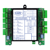
Table 1: Two Condenser Head Pressure II Module
Inputs & Outputs
General
The following inputs and outputs are available on the Two
Condenser Head Pressure II Module. See Table 1 below to
reference the Input/Output Map.
Stand-Alone Input Commands
Condenser Fan A On/O
A 24 volt signal to Binary Input #1 initiates the Condenser Fan A
Enable function. Typically, the source for this signal is the “Y”
call from the thermostat calling for a compressor to run.
Reversing Valve On/O
A 24 volt signal to Binary Input #2 indicates the reversing valve
has been energized and initiates the Reversing Valve Enable On
indication function. Typically, the source for this signal is the
“O” call from a thermostat or other controller.
Condenser Fan B On/O
A 24 volt signal to Binary Input #3 initiates the Condenser Fan B Enable
function. Typically, the source for this signal is the “Y” call from the
thermostat calling for a compressor to run.
Head Pressure Setpoint
The Head Pressure Setpoint is set using the OPTIONS Dip
Switches. See Table 2. The Default Setpoint for an Air Cooled
Condenser is 340 for 410-A refrigerant. The Default Setpoint for
a Water Cooled Condenser is 235 for 410-A refrigerant. Set the
OPTIONS Dip Switch to 0 if using these Default Settings. See
“ADDRESS Dip Switch” below. You must cycle power after
setting Dip Switch values.
NOTE: The only setpoint available for adjustment by
the contractor is the Head Pressure Setpoint.
The rest of the setpoints described can only be
changed by the factory.
ADDRESS Dip Switch Settings for Condenser Type
Selection
When using the OPTIONS Dip Switch to set the Head Pressure
Setpoint, you must also set the ADDRESS Dip Switch to
designate the type of condenser you are using.
Set ADDRESS Dip Switch 1 to ON for a Water Cooled Condenser
or to OFF for an Air Cooled Condenser.
If set to ON for a Water Cooled Condenser, the Analog Condenser
Output Signal will be 2-10 VDC for the Water Valve. If set to
OFF for an Air Cooled Condenser, the Analog Condenser Output
Signal will be 0-10 VDC for the Condenser Fan.
You must cycle power after setting Dip Switch values. See
Figure 3 or 4 for ADDRESS Dip Switch location and Table 3
for Setting information.
Binary Inputs
1
Condenser Fan A On/O (24 VAC Wet Input)
2
Reversing Valve On/O (24 VAC Wet Input)
3
Condenser Fan B On/O (24 VAC Wet Input)
Binary Outputs
1
Condenser A Enable Relay
(Dry Contact Output Rated for 24 VAC)
2
Reversing Valve A Enable
(Dry Contact Output Rated for 24 VAC)
3
Condenser B Enable Relay
(Dry Contact Output Rated for 24 VAC)
4
Reversing Valve B Enable
(Dry Contact Output Rated for 24 VAC)
Analog Inputs
1
Head Pressure #1 (0-667 PSI Sensor)
2
Head Pressure #2 (0-667 PSI Sensor)
3
Head Pressure #3 (0-667 PSI Sensor)
4
Head Pressure #4 (0-667 PSI Sensor)
Analog Outputs (0-10 or 2-10 VDC)
1
Condenser Signal A (AOUT 1)
2
Condenser Signal B (AOUT 2)
PWM Inputs
1
ECM 142 PWM Input (0-100% Duty Cycle)
2
ECM 142 PWM Input (0-100% Duty Cycle)