Conguring the Controller
Conguration
Analog Input #2
This is the input conguration screen used for the Supply Water Tem-
perature sensor (TW Supply Water”) on Analog Input #2 (AIN2). Item
#1 in Figure 11 indicates the Supply Water Temp sensor is congured
for a thermistor type sensor with a Fahrenheit output. All the other
congurations are the same as described for the previous conguration
of the Outdoor Air Temperature sensor except no broadcasting of the
signal is required as was done with the Outdoor Air Temperature Sensor.
Analog Input #3
This is the input conguration screen used for the Return Water Tem-
perature sensor (“TW Return Water”) on Analog Input #3 (AIN3). Item
#1 in Figure 12 indicates the Return Water Temp sensor is congured
for a thermistor type sensor with a Fahrenheit output. All the other
congurations are the same as described for the previous conguration
of the Supply Water Temperature sensor.
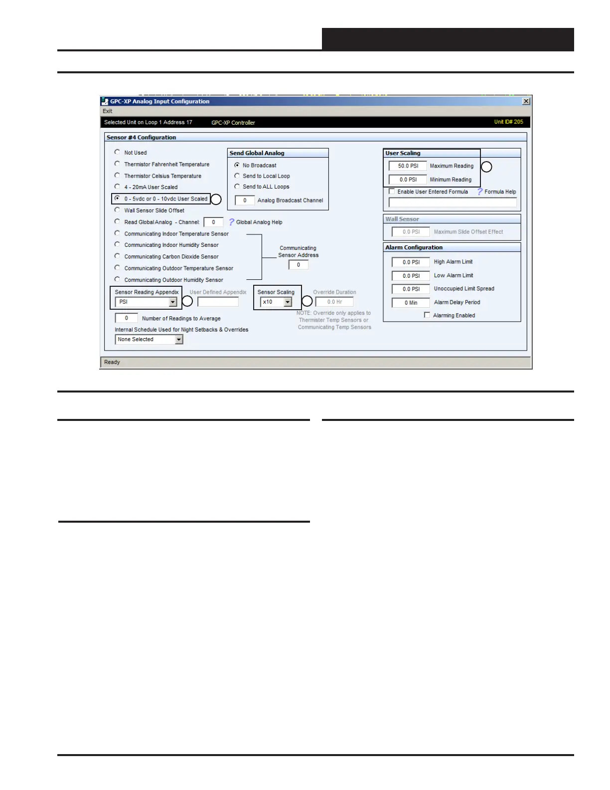
Analog Input #4
This is the input conguration screen used for the Differential Pressure
Sensor (“Loop Pressure”) when used. It is located on Analog Input #4
(AIN4). Either a Differential Pressure Sensor or a Differential Pressure
Switch is required for the Loop Controller operation. If a Differential
Pressure Switch is used instead, it is wired to the Binary Input #2 (BIN2)
which is described under the Binary Input #2 information section that
follows.
Item #1 in Figure 13 indicates the Differential Pressure sensor is
congured for a 0-5 VDC type sensor. This is the requirement for the
sensor WattMaster offers. Yours may be different. Congure the sensor
accordingly.
Item #2 indicates that the sensor reading will be shown in PSI.
Item #3 indicates the Sensor Scaling has been congured to “10” which
will show tenths of a PSI on the screen. So at a 30.47 PSI actual pressure
signal from the sensor the screen would show 30.5 PSI.
Item #4 indicates the User Scaling has been congured to “50 PSI”
maximum reading and “0” PSI Minimum Reading. This should be set
to the range of the sensor you are using.
Figure 13: AIN4 Sensor Screen
1
2 3
4
17
WSHP Loop Controller GPC-XP Guide