Conguring the Controller
Conguration
Binary Input #7
In Figure 23 Item #1 it indicates that Binary Input #7 (BIN7) is not used
in this typical Central Plant Controller conguration. Your application
may require its use and it can be congured as needed.
Binary Input #8
In this example this is the input conguration screen for the Emergency
Shut Down (“Emerg Shut Down”) Binary Input #8 (BIN8). Item #1
in Figure 24 indicates the “Emerg Shut Down” input is congured for
a normally closed contact. This would typically be a contact from a
safety device such as a smoke detector or re stat. When this contact
is activated it would open causing an emergency sequence to initiate.
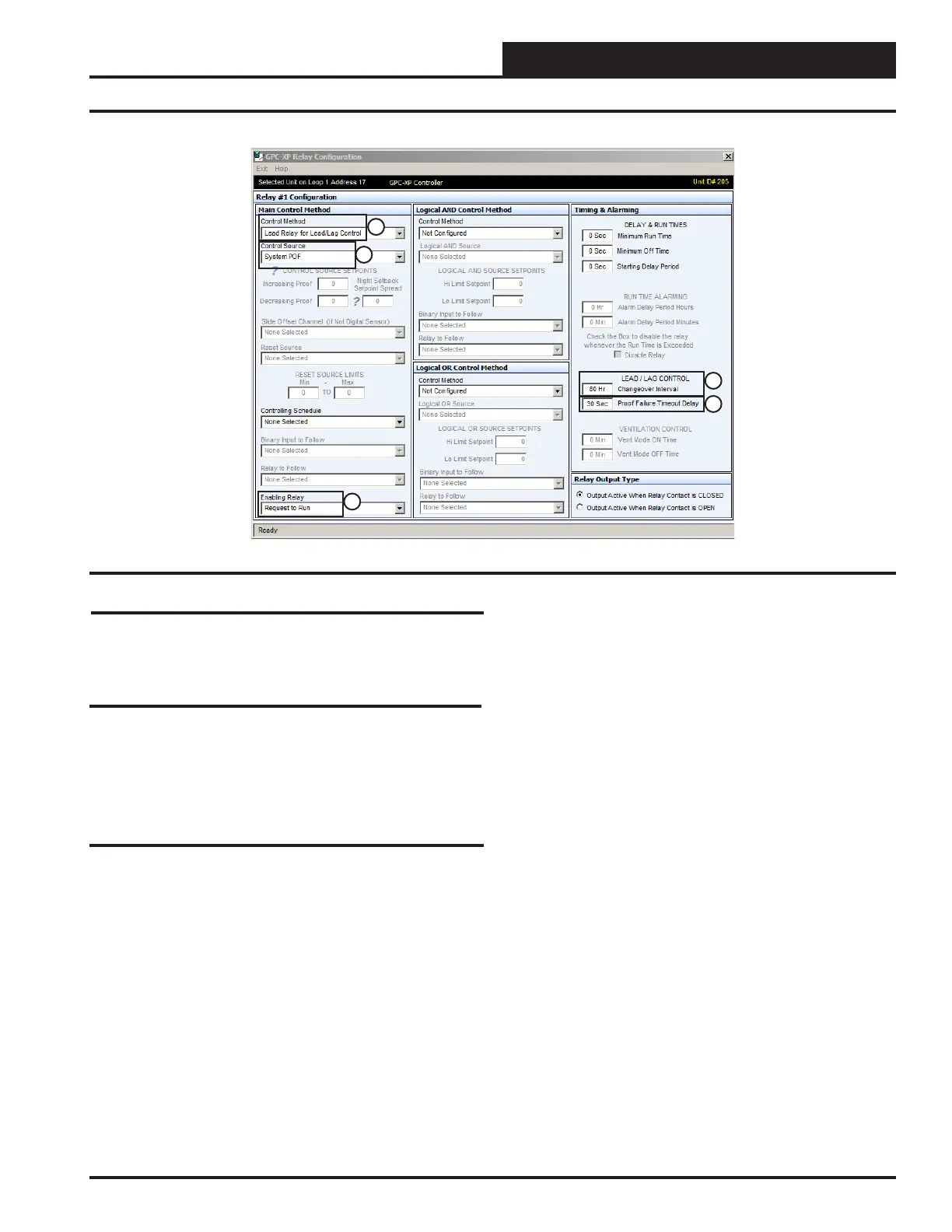
Relay Output #1
In this example Relay Output #1 is congured for “System Pump 1”. In
Figure 25 Item #1 it indicates it has a Main Control Method of “Lead
Relay for Lead/Lag Control”. This means it is the “Lead Pump Relay”
for Lead/Lag type system pump control.
Item #2 indicates the Control Source for this relay will be the “Proof
Of Flow” switch (BIN3). The System Pump is congured with a 30
second Proof Failure Timeout Delay shown in Item #5. This means the
pump Relay Output #1 will activate and “System Pump 1” will have 30
seconds to bring the system water pressure to the setting required, for
the “Proof Of Flow” binary input to be activated. If after that time the
P.O.F. switch doesn’t activate Relay Output #1 will be deactivated and
Relay Output #2 (System Pump 2) will be activated.
It also has a Enabling Relay of “Request To Run” as shown in Item #3.
The “Request To Run relay output is congured on Relay #7.
Item #4 is the “Changeover Interval” for the Lead/Lag Pump sequence.
In this example it has been congured to switch from “System Pump 1”
(Lead) to “System Pump 2” (Lag) after 80 hours of runtime on “System
Pump 1”. Item #5 is the “Proof Failure Time Out Delay”. This is set
for the amount of time that you want the pump to run before a failure
of the “Proof of Flow” binary input shuts down the pump. In this case
it is set to 30 seconds.
With this conguration sequence “System Pump 1” (Relay #1) or “Sys-
tem Pump 2” (Relay #2) will activate when the “System P.O.F.” switch
(BIN3) is activated and the “Request To Run” relay output (Relay #7)
is active.
If the “Request To Run” relay output (Relay #7) is inactive (Relay #1)
will deactivate, turning off “System Pump 1” (or “System Pump 2” if
it is running instead).
If either System Pump 1 or 2 has a Proof Of Flow failure when the
specied pump is supposed to run, an alarm will become active for that
system pump.
To reset a Lead/Lag failure alarm, click on the ALARM button in the
upper right hand corner of GPC-XP Status Screen. When the GPC-XP
Alarms Screen comes up, click on the “Reset Lead/Lag” button, then
exit the screen. The alarm will clear and, the pump with the least amount
of run time will start.
All the settings above will be automatically be applied to the “System
Pump 2” on Relay Output #4 after the “Changeover Interval” for “System
Pump 1 has occurred or System Pump 1 has a “System P.O.F” failure.
Figure 25: Relay Output #1 Screen
1
2
3
4
5
25
WSHP Loop Controller GPC-XP Guide