Conguring the Controller
Conguration
Analog Input #5
In this example this is the input conguration screen for the Boiler Loop
Temperature sensor (“Boiler Loop Temp”) when used on Analog Input
#5 (AIN5). Item #1 in Figure 14 indicates the Boiler Loop Temperature
sensor is congured for a thermistor type sensor with a Fahrenheit output.
All the other congurations are the same as described for the previous
conguration for the Supply Water Temperature sensor.
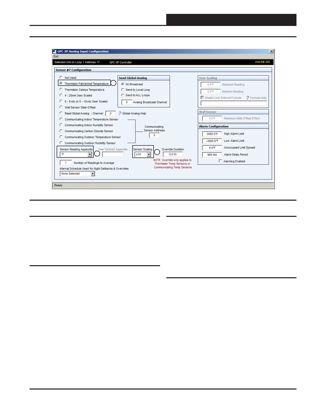
Figure 16: AIN7 Sensor Screen
Analog Input #7
In this example this is the input conguration screen for the cooling tower
Sump Water Temperature (“Sump Temp”) sensor when used, located
on Analog Input #7 (AIN7). Item #1 in Figure 16 indicates the Sump
Water Temperature sensor is congured for a thermistor type sensor
with a Fahrenheit output.
All the other congurations are the same as described for the previous
conguration of the Supply Water Temperature sensor.
Analog Input #8
Analog Input #8 (AIN8) is not congured in this typical Central Plant
Controller conguration but could be used for any other sensor applica-
tion your project may need.
Analog Input #6
In this example this is the input conguration screen for the Outdoor
Air Humidity sensor (“OAS Humidity”) when used, located on Analog
Input #6 (AIN6). Item #1 in Figure 15 indicates the “OAS Humidity”
sensor is congured for a 0-5 VDC signal sensor.
Item #2 in Figure 15 indicates the sensor reading will be in RH percent
and item #3 indicates it will be scaled to a factor of 10 so that tenths of
a percent will be shown in its display. The Outdoor Air Humidity Sensor
would typically be used for information only and would generally not
be used as a control input for the Central Plant Controller.
Item #4 indicates the User Scaling for the sensor has been congured to
“100.0 RH % ” maximum reading and “0.0 %” Minimum Reading. This
should be set to the range of the sensor you are using.
1
2
3
19
WSHP Loop Controller GPC-XP Guide