Conguration
Conguring The Controller
Alarm Notication
The GPC-XP can generate alarms for remote alarm notication if alarms
have been enabled and Prism 2 is connected and running 24 hours a day.
If an alarm condition occurs, the <ALARM> button in the upper right
hand corner of the GPC-XP Controller Status Screen will light up. See
Figure 37. If no alarm(s) exists, the button will be gray. See Figure 38.
Figure 38: No Alarms Button
Individual alarms will also be indicated with a bright red alarm bell icon
in the Analog Inputs Status, Binary Inputs Status, and Relays Status
Windows. See Figure 39.
Figure 39: Analog Inputs Status, Binary Inputs
Status, and Relay Status Alarm Icon
Alarm
Indicator
Alarm
Indicator
Alarm
Indicator
Conguring and Enabling Alarms
Alarms are congured and enabled in the Analog Inputs Conguration
Windows, Binary Inputs Conguration Windows and Relay Congura-
tion Screens. See these previous sections conguration screens to see
alarm settings that are available.
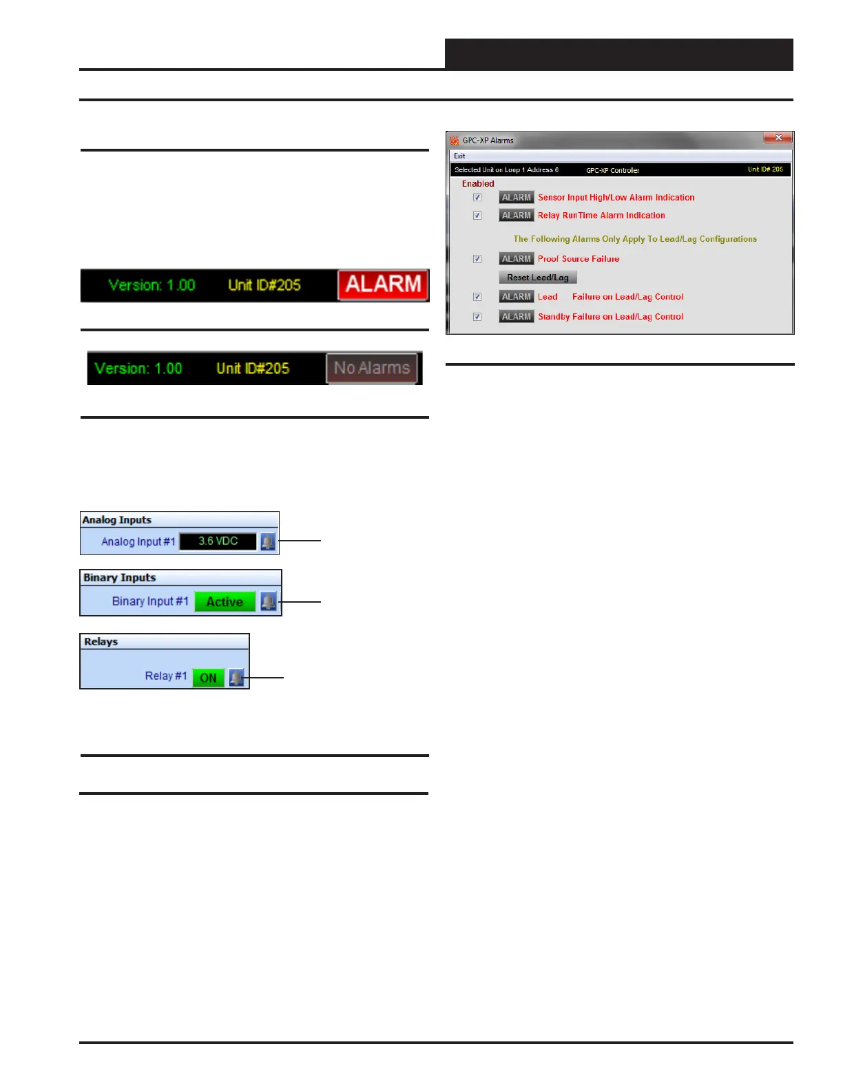
Alarms are also enabled in the GPC-XP Alarms Window. To con-
gure alarms, click on the <ALARM> or <No Alarms> button in the
upper right hand corner of the GPC-XP Controller Status Screen (Figure
7, page 14). The GPC-XP Alarms Window will open. See Figure 40.
Figure 37: ALARM Button
Figure 40: GPC-XP Alarms Window
Click the Enabled box beside any Alarm you wish to enable. When that
alarm condition occurs, the <ALARM> button in the upper right corner
of the Main Prism Screen will turn bright red. This selection will also
allow that Alarm to send out an email notication if your system is set
up for that function. See the Prism 2 Technical Guide for instructions
on setting up email alarm notications.
Due to the quantity of Inputs and Outputs on the GPC-XP, alarms have
been grouped into ”Sensor Input High/Low Alarm Indication” and
“Relay Run Time Alarm Indication.”
The remaining 3 alarm indicators apply strictly to Lead/Lag Relay
operations. The Proof Source Failure indicator isn’t limited to ow
monitoring. It applies to any type of proof of operation your Lead/Lag
requires whether it is Temperature, CFM - Airow, PPM – Parts Per
Million content, etc.
If the proof source doesn’t meet the requirements in the programmed
amount of time, the system switches to the standby output and gener-
ates the proof alarm and either the Lead or Standby alarm, depending
on which relay caused the condition.
If either or both Lead/Lag Relays generate an alarm, normal operation
can be restored by clicking the <Reset Lead/Lag> button. Clicking
the <Reset Lead/Lag> button will restart the system using the relay
with the least amount of accumulated run time. Both do not have to be
in an alarm state for you to reset the lead/lag operation. If the system
has switched to the standby output, it can be restored to the lead output
if you want to test it again or repairs have been made and you just want
to restore normal operations.
If both outputs generate an alarm, they will not attempt to activate again
until the <Reset Lead/Lag> button has been clicked. This is to protect
the equipment from possible severe damage if an output is attempting
to operate damaged equipment.
37
WSHP Loop Controller GPC-XP Guide