10
GAS PIPING
Size gas piping to supply the unit with 6" to 10.5" water
column pressure for natural gas or 11" water column
pressure for propane when all gas consuming devices in
the building connected to the same gas system are
operating. Install piping in accordance with local codes,
the piping must conform with the latest ANSI-Z83.8B
National Fuel Gas Code; in Canada, Current Standard
CAN / CGA-2.6B-MØØ, Installation Codes for Gas
Burning Appliances and Equipment.
Some utility companies will require pipe sizes larger
than the minimum sizes listed.
NOTE: Codes may require the use of a manual main
gas shut-off valve and union, (furnished by others)
installed in the gas line external to the unit.
GAS PIPING is to be supported DIRECTLY AT CON-
NECTION TO UNIT and must not be strained or bent
and shall be supported by metal straps, blocks or hooks.
Pipe joint compounds used on all gas piping connections
shall be resistant to the action of petroleum gases.
An 1/8" NPT plugged tap is required immediately ahead
of the unit gas control valve.
All piping connections shall be checked with a soap
solution for gas leaks before operating the appliance.
INSTALLATION continued
▲
!
CAUTION
Some soaps used for leak detection are
corrosive to certain metals. Carefully
rinse piping thoroughly after leak
test has been completed.
▲
!
WARNING
DO NOT USE OPEN FLAME OR OTHER
SOURCE OF IGNITION FOR LEAK TESTING.
When pressure testing the gas supply piping,
the furnace must be isolated or disconnected
by closing the individual manual shut-off valve
from the gas supply. Gas valves can be
damaged if subjected to more than
0.5 psig pressure.
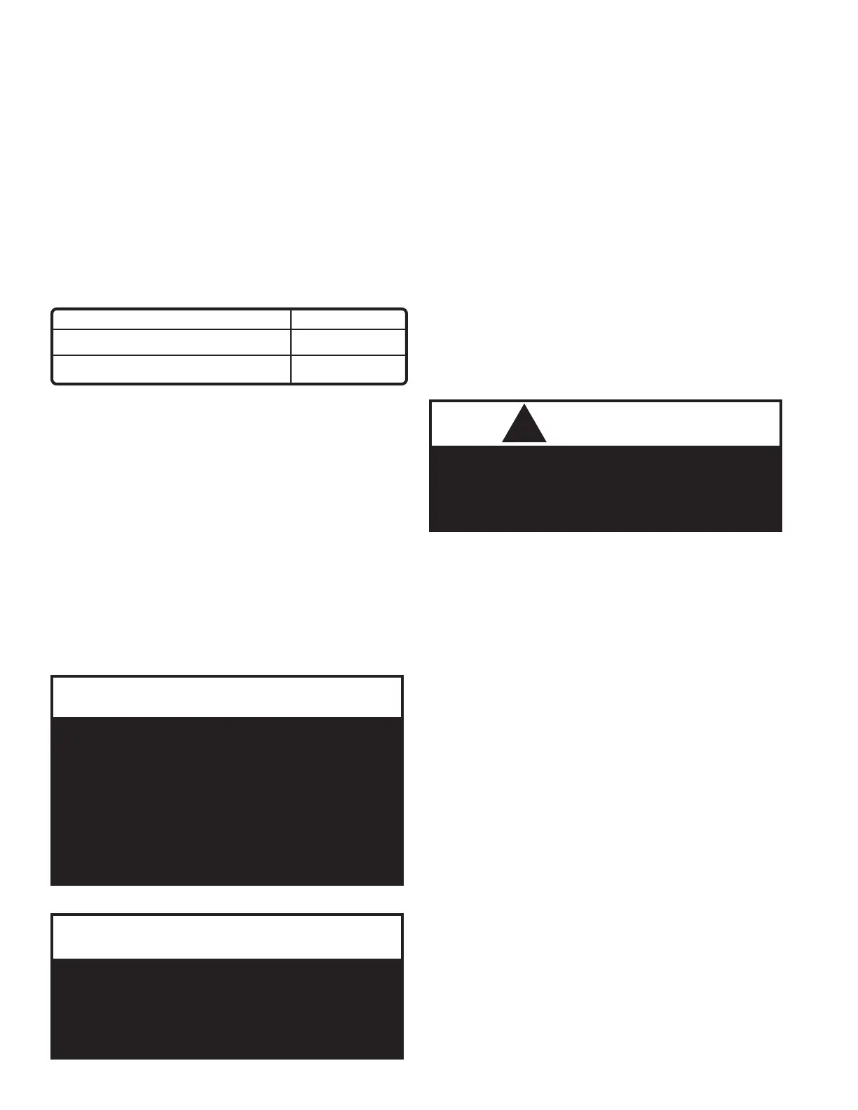
HEAT EXCHANGERS
PIPE SIZE
GAS PIPING SIZES
(8) - Gas Heat Exchangers or Less
2"
(10) to (14) - Gas Heat Exchangers
3"
The furnace must be isolated by closing the manual shut
off valve or disconnected from the gas supply piping
during pressure testing of the piping system with pres-
sures in excess of 1/2 PSIG.
The flow of combustion and ventilating air shall not be
blocked or otherwise obstructed in any way.
NOTE: All gas-fired heat exchangers are completely
tested at the factory before shipment. This will remove
nearly all of the oils that have been used in the manufac-
turing process, however, trace amounts may remain.
When performing the initial start-up at the jobsite, it is
highly recommended that people or any other living
animals, that may be sensitive to the residual odors or
gases, NOT be present in the conditioned space during
the start-up. In all cases, including the initial factory
firing and testing, any of the gases will be under the
acceptable level of concentration for human occupancy.
After electrical power is turned on, set unit controls for
heating, and check for operation.
When checking burner operation, flames should be
observed as blue with slight or no yellow tipping. There
should be no sign of flames floating or lifting off or away
from the main burners.
NOTE: In case emergency shut down is required, turn
off the main manual gas shut-off valve and disconnect
main electrical power to unit. These devices should be
properly labeled by the installer.
Those sensitive to odors or gases from trace
amounts of residual oils should NOT be present
in the conditioned space during the start-up
of a gas-fired installation.
!
WARNING
GAS PRESSURE REGULATOR & OVER-PRESSURE
PROTECTION DEVICE
On applications where gas service to the unit is greater
than 10.5"w.c. and less than 2-psi, a gas pressure regu-
lator must be installed.
At supply pressures in excess of 2-psi and less than 5-
psi, ANSI Z21.80 line regulator standard requires a
means (an over-pressure protection device / OPD) to
limit the downstream pressure to 2-psi maximum, in the
event of regulator failure.
In compliance with the ANSI Standard, installations
exceeding 2-psi or less than 5-psi nominal require a
tested and approved over-pressure protection device for
use with the regulator.
For proper heater operation, pressure to the regulator
MUST NOT BE greater than 5-psi.