9
ELECTRICAL
Check the unit data plate voltage to make sure it agrees
with the power supply. Connect power to the unit
according to the wiring diagram provided with the unit.
The power and control wiring may be brought up through
the utility entry. Protect the branch circuit in accor-
dance with code requirements. Control wires should not
be run inside the same conduit. The unit must be
electrically grounded in accordance with the current
National Electric Code, ANSI / NFPA No. 70. In Canada
use current C.S.A. Standard C22.1 Canadian Electric
Code Part 1.
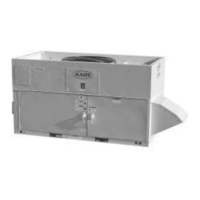
Power wiring is to the unit terminal block or main
disconnect. All wiring beyond this point has been done
by the manufacturer and cannot be modified without
effecting the unit's agency / safety certification.
INSTALLATION continued
AIRFLOW IS TO BE ADJUSTED AFTER INSTALLA-
TION TO OBTAIN AN AIR TEMPERATURE RISE
WITHIN THE RANGE SPECIFIED ON THE RATING
PLATE.
START-UP TECHNICIAN MUST CHECK BLOWER
MOTOR AMPERAGE TO ENSURE THAT THE AM-
PERAGE LISTED ON THE MOTOR NAMEPLATE IS
NOT EXCEEDED.
▲
On three phase units the rototation must be
checked on ALL MOTORS AND COMPRESSORS.
SCROLL COMPRESSORS ARE DIRECTIONAL.
Rotation must be checked on start-up by a
qualified service technician using
suction and discharge gauges.
Scroll compressors will FAIL if run in the wrong
direction. Blower and condenser rotation
should be checked and only be altered if
necessary at the power connection.
! CAUTION
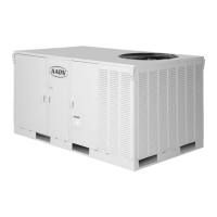
COMPRESSOR COMPARTMENT EXHAUST FAN
COMPRESSOR COMPARTMENT EXHAUST FAN
Prior to unit operation the compressor compartment
exhaust fan shipping support MUST BE removed from
the exterior of the unit.
The exhaust fan also requires the installation of the
exterior rain hood provided with the unit.
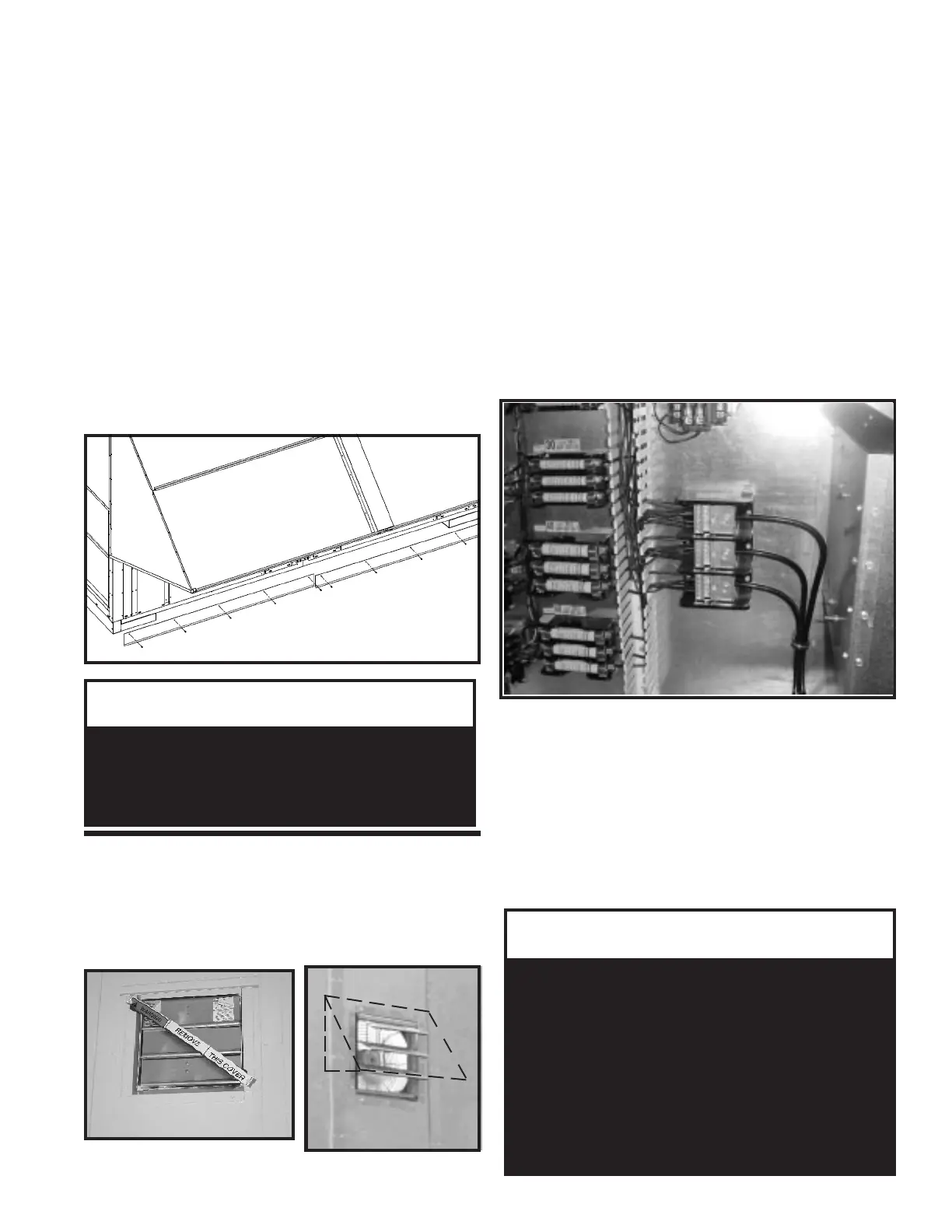
RL ‘D & E’ 142” Wide Units
End Flashing Installation Detail
On AAON ‘RL’ (142” wide - D & E cabinet units) the
cabinet width will overhang the trailer on each side.
In order to secure and protect the unit during transit the
sheetmetal end flashings have been removed from the
unit. The slot created at each end of the unit at the base
allows for the unit to set firmly on the trailer deck.
Sheetmetal flashings are shipped loose with the unit and
once the unit is set into place the flashings MUST BE
installed on each end of the unit to complete the finished
seal at the base. The flashings are unit specific and
designed to cover the slot at each end of the unit to
prevent water run-off into the curb.
Failure to attach and seal the end of the unit with the
flashings will result in water leakage into the curb.
▲
In order to prevent water leakage into the roof
curb, the factory provided sheetmetal flashings
MUST BE attached to the unit base to cover
the shipping slots at both ends of the unit.
!
IMPORTANT
FACTORY SUPPLIED
END FLASHINGS
- TYPICAL FOR BOTH
ENDS OF UNIT -