15
Axial Flow Fans
Multi-Wing Z Series Fans
Blade Pitch Angle Setting Instructions
Before You Begin:
To maintain balance of fan:
• Mark the hub castings across a joint, so the fan hub can
be reassembled in the same orientation.
• Mark the location of any balancing weight. Balancing
weight will be on the outer bolt circle, in the form of
washers, and/or longer bolts, or an additional
balancing nut.
• Number the blades and blade sockets, so that they are
replaced into their original position.
If possible, note the location of the pitch setting pin in the
blade socket, and whether pin is located in the Hub or
Retainer half of the fan.
STEP 1 - Determine Boss Location Code: “A” or “B”
The boss is the center section of the hub through which
the fan is mounted to the shaft, and typically contains
either setscrews or a center-tapered hole where the
bushing inserts.
Select boss location A or B:
A is the boss on air inlet, including AS configurations.
B is the boss on air discharge, including BS.
For flange mounted fans, use boss location A for R
rotation fans, and boss location B for L rotation fans.
STARTUP continued
STEP 2 - Find Blade Pitch Angle:
( 20, 25, 27.5, 30, 32.5, 35, 37.5, 40, 45 or 50 )
• Carefully disassemble fan on flat surface and note in
which groove the pin is located. Refer to groove number
code diagram.
• Using diagrams in step 5, determine if the pin was in
the hub (HUB) or retainer side (RET) of fan.
• Using table in step 4, find the possible blade pitch.
• Using table in step 3, select your blade angle based on
whether your pin was in the HUB or RET.
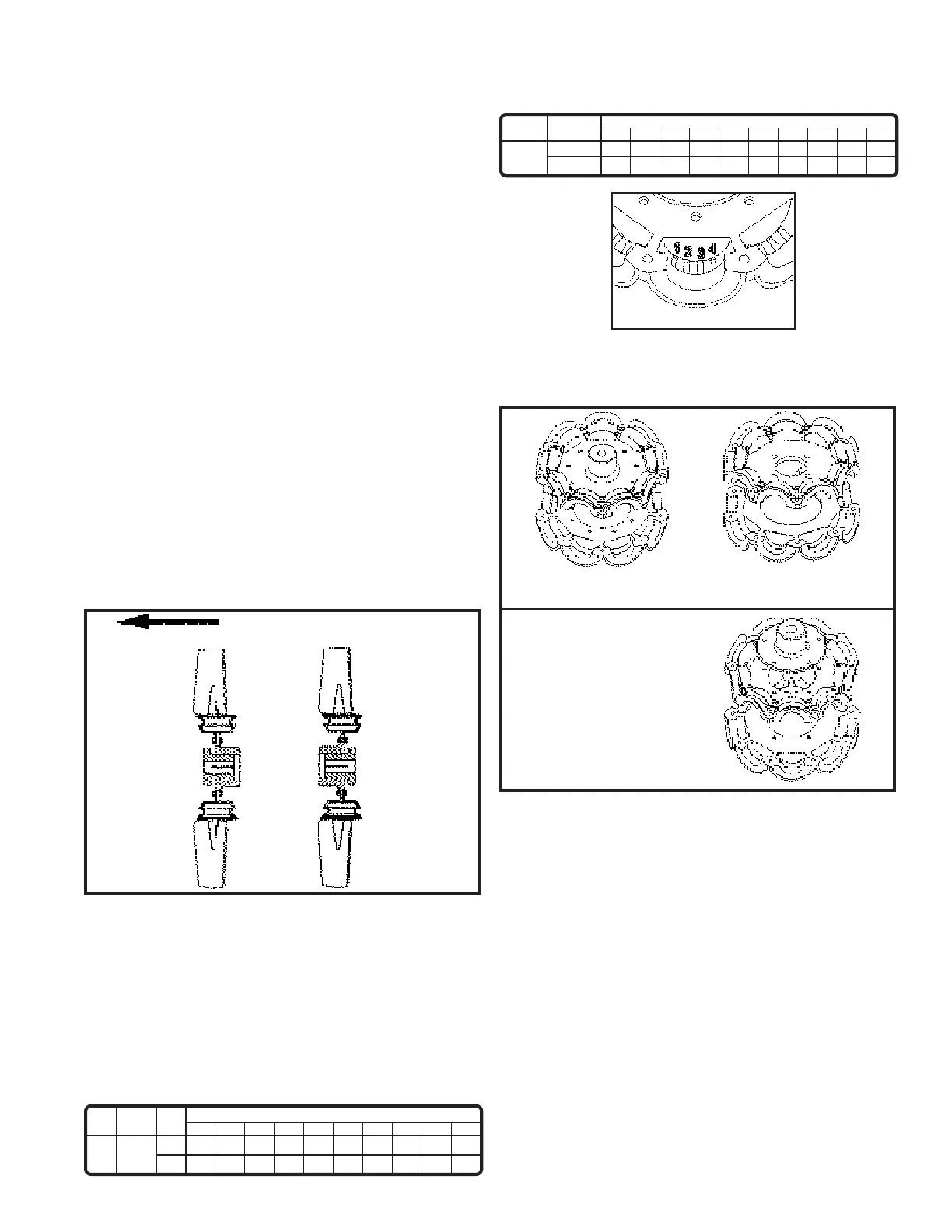
STEP 5 - Final Assembly
Definition of HUB and RET for purposes of instructions.
For 2-piece hubset:
Bottom half is the RET
or retainer ring.
Top half is the HUB
For 3-piece hubset:
Top two pieces together are
considered the HUB and
bottom piece is considered
the RET of retainer ring.
Using the HUB or RET code found in Step 3:
If code is HUB, place the hub down on work surface first
(one or two pieces, depending on above).
If code is RET, place one retainer ring only down on the
work surface first. (A weighted coffee can could be used
to elevate the fan from the work surface).
Using the groove number, place the locking pin in the
groove number that was found in Step 4.
Insert Blades:
• Place the blade over the pin in the hub/retainer blade
socket, so that the pin also fits into the appropiate pitch
angle groove in the blade.
• Repeat for all blades.
• Assemble hubset together, aligning the match marks
that were made.
• Replace any balancing weight to its original position.
• To finish, tighten the bolts in a cross pattern to 5 to 6
foot-pounds of torque.
STEP 4 - Determine Groove Number: 1 or 2 or 3 or 4
Type
20°
Rotation
Blade Pitch Angle - Degrees
25
27.5
30
32.5
35
37.5
40
45
50
5Z
R
1
4
- - -
- - -
- - -
- - -
2
3
3
2
4
1
4
1
3
2
2
3
1
4
L
Type
20°
STEP 3 - Determine Hub/Retainer Code: “HUB” or “RET”
Rota-
tion
Boss
Pos.
Blade Pitch Angle - Degrees
25
27.5
30
32.5
35
37.5
40
45
50
5Z
R or L
A
B
HUB
RET
- - -
- - -
- - -
- - -
HUB
RET
HUB
RET
HUB
RET
HUB
RET
HUB
RET
HUB
RET
HUB
RET
DIRECTION OF AIRFLOW
BOSS & BUSHING
POSITION “AS”
BOSS ON
AIR INTAKE
BOSS & BUSHING
POSITION “BS”
BOSS ON
AIR DISCHARGE
GROOVE No. CODE CHART
 Loading...