8
Unit Section Splicing
AAON ‘RL’ units are designed and built according to unit
size and / or job specifications. Some applications may
require the unit to be built and shipped in two separate
sections. The following illustrations are provided as
practical guidelines for splicing the two sections.
It is recommended to lift and set the largest section first,
checking for the correct location and position. In order to
simplify the connection of the two sections, it is impor-
tant, once the first section is in place, to position and set
the second section AS CLOSE AS POSSIBLE to the first
section. The least amount of travel between the two
sections will allow the use of a “come-a-long” tool, (one on
each side of the unit, connected at the base slots) to
equally pull the second section against the first section.
The two sections must be tightly adjoined before the
splicing parts can be installed.
Because the adjoining section is “unit specific”, all parts
required for splicing the sections together are provided
from the factory.
Once the unit is completely assembled, it is important to
visually inspect all exposed areas and fill any gaps with
Butyl caulking.
NOTE: Installation of splice plates are typical for both
sides of unit.
INSTALLATION continued
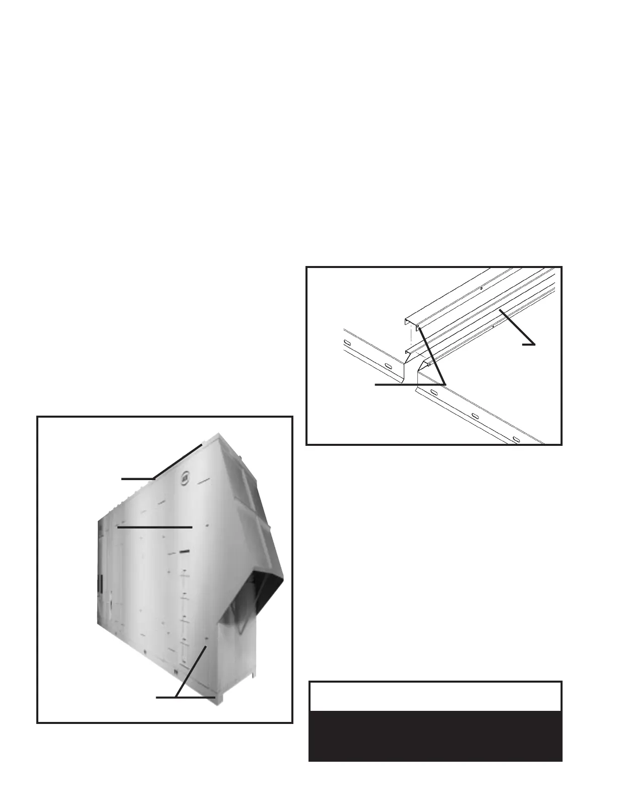
During the splicing process it is equally important to
check the alignment of the roof and the connecting
flange. Prior to connecting the sections, to create a water
tight seal, Butyl caulking must be applied between the
two roof flange sections.
The roof splice cap is provided from the factory and must
be installed over the two sections connecting flange and
secured with screws along the length of the cap.
NOTE: ATTACH SPLICE CAP WITH SCREWS FROM
EACH SIDE OF THE CAP ONLY.
DO NOT INSTALL SCREWS FROM THE TOP.
Once the splice cap is secured into place, Butyl caulking
must be used to seal the perimeter of the cap against the
roof of the unit.
IMPORTANT
RELATED ELECTRICAL REQUIREMENTS
Before attempting to make wire connections from section
to section it is important to refer to the specific wiring
diagram located in the unit controls compartment to
obtain additional details related to the wiring of the unit.
The adjoining section is factory wired and ready for field
connection. The electrical wiring is unit specific and
designed according to the overall unit configuration.
A factory supplied and mounted terminal block is located
in the main section of the unit that must be used in
making the rough-in wire connections.
Each wire being spliced from section to section is tagged
at both ends according to its termination. Note that
junctions for wiring the sections together are separated
according to voltage.
▲
All wire terminations MUST BE made before
applying power to the unit. The unit will not
operate unless all circuits are made.
!
CAUTION
UNIT BASE AND SIDES
STEP 1:
ALIGN BASE RAIL
& SIDES OF SECTIONS
- TYPICAL TWO SIDES -
NOTE: FACTORY INSTALLED
NEOPRENE GASKET APPLIED
ON ENDS OF BOTH SECTIONS
STEP 3:
FILL POST SEAM WITH
BUTYL CAULKING
STEP 4:
ATTACH SPLICE PLATE
TO OUTSIDE OF POST
(screws provided)
TO COVER SEAM
STEP 5:
APPLY BUTYL CAULKING
TO ALL SEAMS
& PERIMETER OF SPLICE
STEP 2:
CHECK ROOF ALIGNMENT
(see detail)
UNIT ROOF FLANGE SPLICE DETAIL
STEP 1:
APPLY BUTYL
CAULKING BETWEEN
SECTIONS OF ROOF FLANGE
- MUST BE A
WATER TIGHT SEAL -
STEP 2:
SET ROOF SPLICE IN
PLACE OVER FLANGE
SECURE WITH SCREWS
FROM THE SIDES.
SEAL PERIMETER WITH
BUTYL CAULKING
NOTE:
DO NOT INSTALL
SCREWS FROM THE
TOP OF SPLICE CAP.