13
▲
!
WARNING
Electric shock hazard. Can cause injury or death.
Before attempting to perform any service or
maintenance, turn the electrical power to unit to
OFF at disconnect switch(es). Unit may have
multiple power supplies.
STARTUP
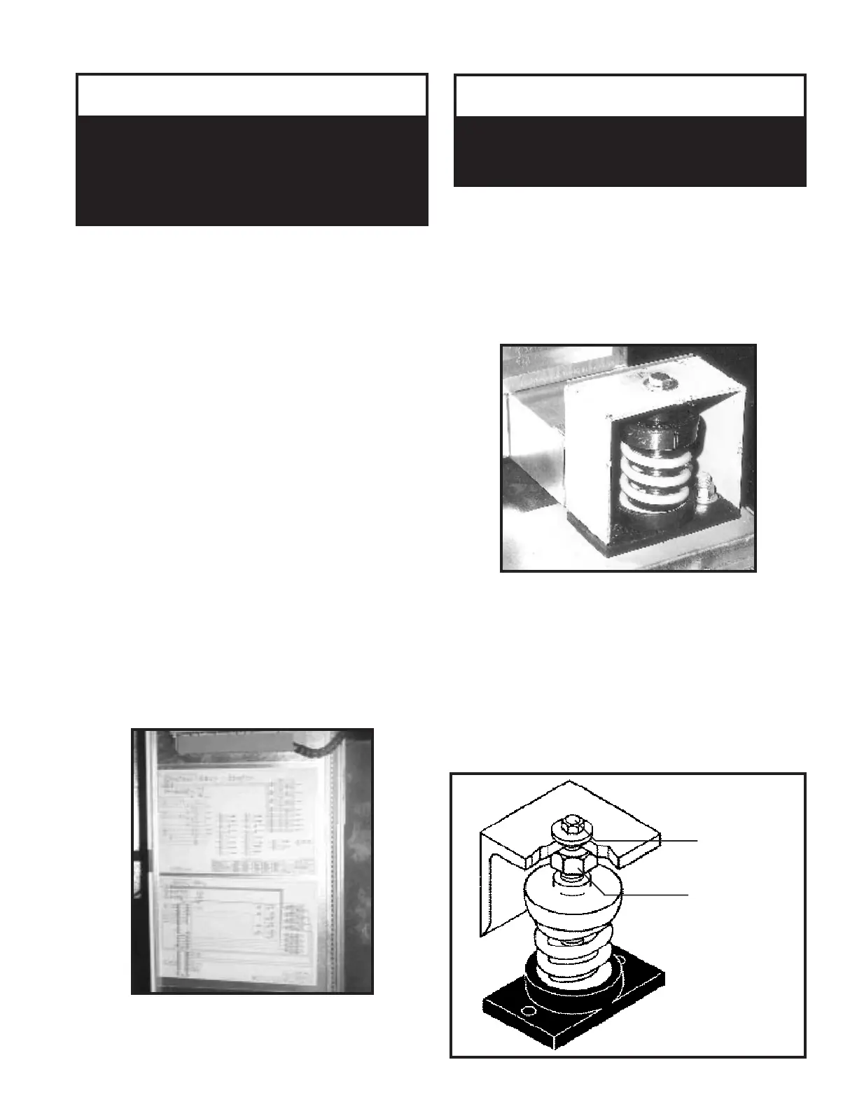
Spring Isolator Adjustment
AAON ‘RL’ units are equipped with spring isolators in
the blower section for vibration attenuation.
Prior to unit shipment the isolators are set in the lock
down position and the blower section deck is resting on a
wood base to protect the unit during transit.
Once the unit is set into place it is important that all of
the isolators are adjusted out of the shipping position and
the shipping material is discarded before the unit is put
into operation.
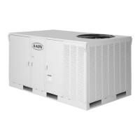
The isolators can be adjusted by first loosening the
locking bolt located on top of the frame. The adjustment
bolt located just below the frame is used to set the spring
into the operating position. After the isolator is set for
operation the locking bolt must be tightened against the
frame.
▲
Vibration Spring Isolators MUST BE
adjusted from the shipping position prior
to unit start up.
!
IMPORTANT
START-UP TECHNICIAN MUST CHECK MOTOR
AMPERAGE TO ENSURE THAT THE AMPERAGE
LISTED ON THE MOTOR NAMEPLATE IS NOT
EXCEEDED.
PRE STARTUP
After the installation and immediately before the startup
of the condenser be sure that these items have been
checked.
1. Verify that electrical power is available to the unit.
2. Verify that any remote stop/start device is request-
ing the condenser to start.
While performing the Startup, use the Startup Form at
the rear of this booklet to record motor amps and any
other comments.
Use the General Check List at the top of the Form to
make a last check that all the components are in place
and the power supply is energized.
NOTE: Condensing fan operation must start with the
first compressor.
Cycle through all the compressors to confirm that all are
operating within tolerance.
When unit is running, observe the system for a complete
operation cycle to verify that all systems are functioning
properly.
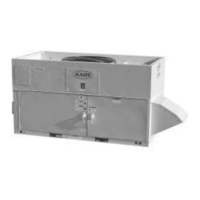
COLOR-CODED WIRING DIAGRAM
VIBRATION
SPRING ISOLATOR
ADJUSTMENT
BOLT
LOCKING
BOLT