- 10 -
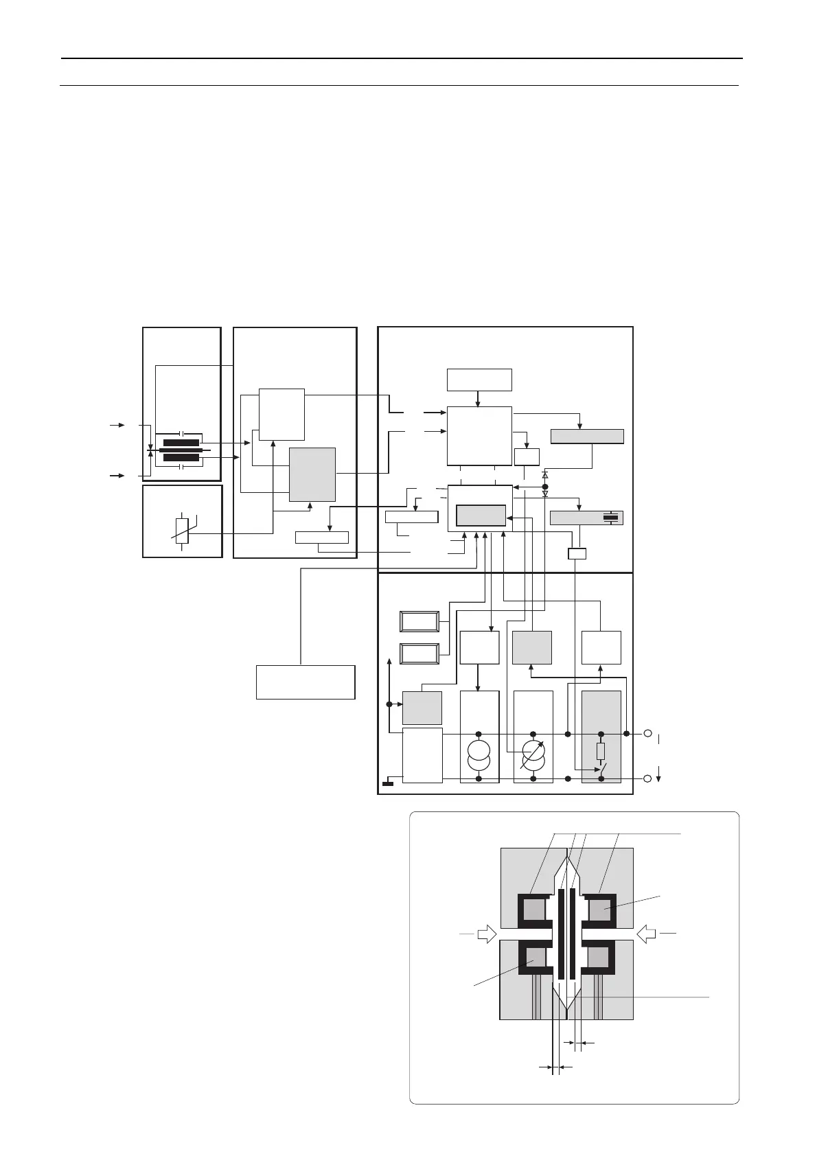
. . . PRINCIPLE OF OPERATION
2600T Safety Transmitter takes advantage of the intrinsic
redundancy of the 2600T series differential inductive sensor.
The two inductive signals are separately detected in the
primary unit by two independent ASICs and separately
elaborated internally to the electronics. Calculations follow
independent flows and they are compared in the microcontroller
in order to validate the output pressure signal. If a difference
between the two measurements is detected the analog output
is driven to a safety condition. Internal diagnostics algorithms
are implemented to check correctness and validity of all
processing variables and the correct working of memories.
A supplementary shut down circuitry provides a safe shut down
when a fault occurs in the analog section of the electronics. The
output stage is also checked by reading back the analog output
signal. The feedback loop is obtained by an additional A/D
converter put at the end of the output stage, which translates
the 4-20 mA signal into a digital form suitable to be compared
by the microcontroller.
Pressure Sensor
The pressure sensor gives the primary input signal to the
electronics. The input pressure is converted in a (micro)
displacement "d" of a metal diaphragm (measuring diaphragm)
whose stiffness determines the URL of the sensor. The
diaphragm displacement changes the gap of a magnetic
circuit, generating the variation of the inductive pick-up detector
constituted of two inductances called L1 and L2. One of the
inductance values increases the other decreases. The
inductance value is measured by forming an oscillator with an
extra capacitor (C1,C2). The oscillation is excited by a pulse
and simultaneously measured by two ASIC5 (see the picture
above). The fundamental frequency of oscillation relates to the
inductance values with the following law: (T=2PI*SQR(LC)).
Temperature Sensor
The temperature sensor measures the temperature of the
pressure sensor. The resulting value is used by the µP for
temperature compensation purposes.
SAFETY 2600T Pressure Transmitters
block diagram
Pressure sensor
Ferrite
L2
L1
P2
P1
Measuring
diaphragm
d1 (gap)
d2 (gap)
ASIC5
(trigger
and
reading)
Primary
Electronics
EEPROM
EEPROM
A/D
converter
ASIC7
µP
Secondary
Electronics "µP"
ASIC5
(only
reading)
T5 Generator
+0.33% / °C
1.watchdog
2.watchdog
&
L1
L2
P1
P1
Pressure
Sensor
Temperature
Sensor
PWM
Filter
TX2
TX1
CE2
CE1
Calibration
Parameter
Sensor
Parameter
Display
Reset
Reset
HART
modem
Tx
4...20 mA
reading
HART
modem
Rx
over-
voltage
detection
DC/DC
Converter
GND
const.
current
generator
3.6 mA
const.
current
generator
0.4...16.4
mA
second
shut
down
>20 mA
4...20 mA
10.5...42 V
Key
Span
Key
Zero
Secondary
Electronics "PS"
VCC
D0...7 A0...9
HARDWARE DESCRIPTION
General hardware description
The electronic hardware structure is described in the following figure.

 Loading...