EasyManua.ls Logo

ABB 2600T-266 User Manual

ABB 2600T-266
96 pages
To Next Page IconTo Next Page
Page #1 background imageLoading...
Page #1 background image
ABB MEASUREMENT & ANALYTICS | OPERATING INSTRUCTION
266 with PROFIBUS PA Communication
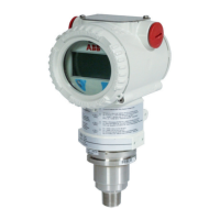
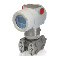
Pressure transmitters
Engineered solutions for all
applications
Measurement made easy
Introduction
The 2600T family provides comprehensive range of
top quality pressure measurement products,
specifically designed to meet the widest range of
applications ranging from arduous conditions in
offshore oil and gas to the laboratory environment
of the pharmaceutical industry.
For more information
Further publications for 2600T series pressure
products are available for free download from
www.abb.com/pressure
266 models

Table of Contents

Questions and Answers:

ABB 2600T-266 Specifications

General IconGeneral
Model2600T-266
TypePressure Transmitter
ManufacturerABB
Housing MaterialAluminum, Stainless Steel
Ambient Temperature Range-40 to 85 °C (-40 to 185 °F)
CertificationsATEX, IECEx, FM, CSA
Measurement TypeDifferential, Gauge, Absolute
Output signal4-20 mA, HART
OutputAnalog
Process Connection1/2" NPT, G1/2, M20x1.5
Electrical Connection1/2 - 14 NPT, M20 x 1.5
Process Temperature Range-40 to 85°C
Protection RatingIP67

Summary

2 Safety

2.1 General safety information

Provides essential safety guidelines for operating the device.

2.2 Improper use

Lists prohibited uses of the device to prevent hazards.

2.3 Technical limit values

Outlines crucial operational limits for safe device performance.

2.7 Qualified personnel

Specifies requirements for personnel performing installation and maintenance.

2.12 Safety information for electrical installation

Outlines safety precautions for electrical connections.

2.13 Safety information for inspection and maintenance

Details safety measures during inspection and maintenance.

5 Mounting

5.1 General

General instructions and considerations before mounting the transmitter.

5.3 Mounting the transmitter

Covers factory configuration and hazardous area considerations for mounting.

5.5 Mounting a Differential Pressure sensor transmitter

Mounting instructions for DP sensor transmitters (266DS, 266MS, 266PS).

5.5.1 Bracket mounting (optional)

Details optional bracket mounting options.

5.6 Mounting a P style pressure transmitter

Mounting instructions for P style transmitters (266G, 266A, 266H, 266N).

5.9 Impulse piping connection for standard instruments

Guidelines for correctly laying out impulse piping.

5.10 Process connections considerations

Guidelines for connecting process lines to the transmitter flange.

5.13 Installation recommendations

Recommendations for impulse piping based on application.

6 PROFIBUS PA Communication Protocol

7 Device introduction

7.2 Transmitter wiring

Covers safety precautions and procedures for wiring the transmitter.

8 PROFIBUS electronics

9 Local push buttons

9.2 Operations

Explains the operation of Zero, Span, and Write Protection buttons.

10 HMI Local Indicator

11 Commissioning

11.1 Correction of the mounting position

How to correct zero shifts caused by mounting position.

11.2 Configuration

Details the configuration of Analog Input blocks via Profibus.

11.2.1 Network configuration

Steps to import GSD file and configure Profibus network.

11.2.2 Device configuration

Explains device parameter access via Profibus communication.

11.4 User setting

Guides on setting up parameters for different measurement types.

Volume measurement setting

User settings for volume measurement configuration.

12 Operations

12.1 Sensor trimming / calibration

How to adjust and calibrate the sensor for accuracy.

13 PILD Algorithm

14 Device Block Diagram

15 Maintenance

15.4 Pressure transducer replacement

Detailed steps for replacing the pressure transducer.

16 Hazardous Area Considerations

16.1 Ex Safety aspects and IP Protection (Europe)

Details ATEX and IP certifications for hazardous areas in Europe.

16.2 Ex Safety aspects and IP Protection (North America)

Details FM Approvals and NEMA ratings for North America.

Appendix A - Device mapping

PRESSURE TRANSDUCER BLOCK (PRTB)

Lists parameters related to the pressure transducer block.

Appendix B – Device diagnostic table

Appendix C – HMI structure

Easy Set-up

Step-by-step guide for initial device setup via HMI.

Device Set-up

Detailed setup options for device configuration via HMI.

Calibrate

Options for local calibration of the pressure sensor.

Appendix D – Troubleshooting

Electronics errors

Lists common electronics faults and their troubleshooting steps.

Pressure Sensor errors

Lists common sensor faults and their troubleshooting steps.

Related product manuals