Do you have a question about the ABB 600T EN Series and is the answer not in the manual?
Explains symbols for Warning, Caution, Note, and Information used in instructions.
Key points to ensure safe operation and handling of the transmitter.
Information regarding the year 2000 compliance of 600T EN Series products.
Overview of the 600T series transmitters and their HART communication capabilities.
Reference information for remote seals and transmitter configuration.
Guidelines for transporting, storing, and handling the instrument.
Details on instrument identification via nameplates and labels (Ref. A, B, C, D).
Design principles for 600T transmitters according to IEC61508 for Safety Related Systems.
Management of functional safety and lifecycle information requirements.
Defining the application target, hazard potential, and relevant laws/standards.
Defining safety functions and process interface requirements.
Allocation of safety functions, I/O systems, structure, programming, and routines.
Details on software development, structure, logic, compilation, testing, and validation.
Requirements for installation, mechanical setup, wiring, and commissioning.
Validating system functionality and guidelines for operation.
Procedures for maintenance, replacement, repair, and management of change.
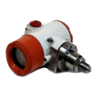
Description of the Primary Unit (process interface/sensor) and Secondary Unit (electronics).
How pressure is converted to diaphragm displacement and temperature is measured.
Conversion of pressure signal to pulse-width signal by ASIC5 and EEPROM1.
Data conversion, compensation, ASIC7, watchdogs, HART modem, and μP functions.
Generators, converters, HART receiver, over-voltage detection, and shut-down circuits.
General warnings and cautions for installation, including hazardous areas and stresses.
Instructions for mounting the transmitter and rotating the secondary unit.
Warnings for hazardous areas, connection integrity, and protective cover.
Details on terminal compartment, ports, signal cable, and power supply wiring.
Guidelines for signal wiring proximity, grounding, and mA testing terminals.
Warnings against ammeter connection and notes for HART communicator use.
Operating voltage range, optional device voltage needs, and loop resistance factors.
Resistance requirements for configuration devices and safety barrier compatibility.
Description of analog and HART signals, including output limits and failure modes.
Terminology for range/span and limitations for calibration.
Transmitter parameters, protection against changes, and operating philosophy.
Enabling/disabling operating modes and required operations between modes.
Overview of calibration methods, preliminary checks, and test equipment.
Step-by-step calibration for gauge and absolute pressure.
Methods for zero suppression and zero elevation.
Notes on accuracy, output reranging, and post-calibration conditions.
Procedure for validating safety functionality after installation.
Annual procedure to maintain Safety Integrity Level (SIL 2).
Warnings regarding process fluids, on-site dismantling, and electronic unit separability.
Step-by-step instructions for safe dismantling and reassembly.
Warnings for flange assembly and cover engagement in hazardous locations.
Warnings for control loop operation and equipment needed for fault finding.
Flowcharts for diagnosing high, low, irregular, or no output issues.
Guidelines for unit replacement and checking transmitter power supply.
Form for recording identification, operating conditions, reason for return, and shipping.
Overview of analog and digital meters, their features, and calibration.
Steps for calibrating output current (4-20mA) and percentage (0-100%).
Switch settings for ZERO, SPAN adjustment, and decimal point position.
Procedure for installing or replacing meters, including warnings.
Safety warnings for hazardous locations and meter removal.
CoMeter features, connection, access to configuration, and notes.
Setting up meter configuration and protecting menus with a password.
Details on ConF AUTO, ConF MANUAL, ConF CURRENT, and ConF PERCENT options.
Overview of transmitter configuration options including CONF, TRIM, REVIEW, PV.
Detailed descriptions of the CONF, TRIM, REVIEW, and PV menus.
Detailed operations within the TRIM menu: Reranging, Loop Test, Output Trim, Zero Adjustment.
Options within the REVIEW menu for viewing transmitter information.
Options within the PV menu for viewing primary, secondary, tertiary, and fourth variables.
Methods for PV-scaling: SET PV ZERO and SET PV VALUE.
Explanation of PV-scaling effects with practical examples.
Warning to put the device in operating condition after calibration.
Description of the built-in surge protection circuit and its function.
Instructions for fitting the surge protector, including cautions and warnings.
Diagrams showing terminal block views with surge protector.
Procedure for fitting surge protector on new terminal blocks with three terminals.
Description of selectable linear and polynomial output functions.
Details on 5th order polynomial functions and application examples.
Polynomials for volume calculation in cylindrical and spherical tanks.
General notes regarding transmitter calibration for level measurement.
Description of output using two 2nd order polynomial functions.
Function activated by a Configuration Tool for testing purposes.
Recalculating LRV/URV based on new percentage input for level measurement.
Examples demonstrating Option 1 (OP Range Low) and Option 2 (OP Range High).
Details on ATEX II 1G certificate, TUV number, code meaning, and application.
Details on ATEX II 1/2 G certificate, CESI number, code meaning, and applications.
Overview of ABB's instrumentation product categories.
Information on ABB's worldwide support services and warranty claim requirements.
Declaration of conformity with EMC directives and relevant standards.
| Brand | ABB |
|---|---|
| Model | 600T EN Series |
| Category | Transmitter |
| Language | English |