Assembly Instructions / A101-H
4 Installing the turbocharger / 4.4 Fastening the turbocharger with a
standard nut
© Copyright 2019 ABB. All rights reserved. HZTL455311P0038_EN Rev.A December 2019
4.4 Fastening the turbocharger with a standard nut
u Fit the nuts and tighten them according to variant 1 or 2 in the table below.
Product Through hole in
bearing casing
[mm]
Fixing screws
[mm]
Variant 1: Tightening
torques [Nm] **)
Variant 2: Hy-
draulic pre-ten-
sioning forces [kN]
A131-H Ø17 M16 280 110
A136-H Ø 21 M20 560 175
Table7: Tightening torque for standard nuts
**) When the turbocharger is mounted on the engine support, the bolt threads and screw
heads must be lightly oiled (assumed friction coefficient µ = 0.12 for tightening torque)
u Remove the lifting gear.
4.5 Connecting the turbocharger
u Connect the cable to the speed sensor (86515).
u Connect all exhaust gas, water and air lines according to the instructions of the engineb-
uilder.
Version with compressor wheel cooling
CAUTION
Failure of compressor wheel cooling
Any prolonged failure of the compressor wheel cooling will shorten the re-
placement interval of the compressor wheel.
u Make sure there is an uninterrupted supply of cooling air during opera-
tion.
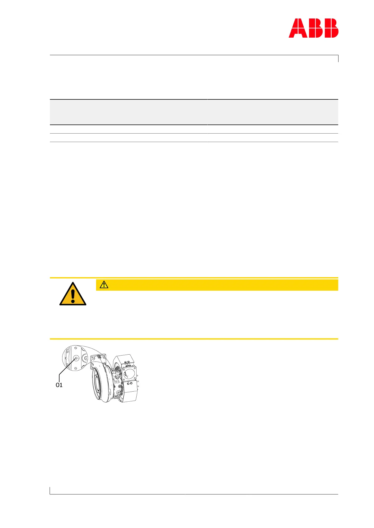
Fig.9: Connecting the compressor cooling air intake
u Remove the lock from the connection for the compressor wheel cooling (01) and fit the
cooling air line.
Page 13 / 17
 Loading...