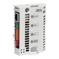
Installation of the module
17
3. At the first end of the MS/TP network, set the DIP switches of
the drive to the ON position to activate the termination of the
drive. The DIP switches are on the left of the EFB connector
(see the figure of step 2).
Note: You can alternatively use the 120 ohm termination resistors
delivered with the module.
See also Connection examples on page 37 and step 9 of this
section.
4. Mount the power connector to the drive’s
internal 24 V DC connection on terminals 10
and 11.
You can also use an external power source.
See the Power cable section on page 14.
The drive can supply 250 mA but the
required current for the router module is
200 mA.
Note: If you use an external power source,
make sure that the power connection does
not exceed the technical specifications of
the router module.
Connect the wires in the order listed in the table below.
RBIP-01 terminal ACH550 terminal Wire
24 V DC 10, 24 V red
GND 11, GND black

 Loading...