ACH580. Also, these examples show how 24VAC can be connected to digital input
on E-Clipse Bypass Control Board.
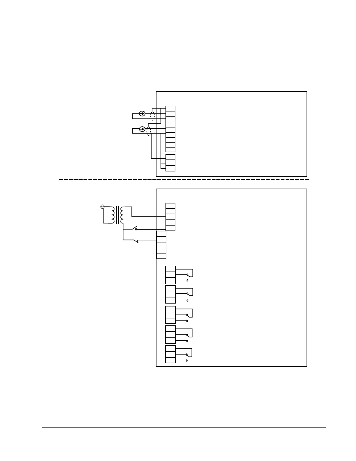
Speed Reference / Process Setpoint
Process Feedback Signal
ACH580 CONTROL BOARD
E-CLIPSE BYPASS CONTROL BOARD
Terminal for Signal Cable Shield
Analog Input Common
Analog Input 2
10V / 10mA Reference Voltage for Potentiometer
Analog Input Common
Analog Input 1
X1
1
1
5
4
3
2
6
2
5
4
3
6
7
10
9
8
11
X2
25
23
22
21
20
24
19
18
17
16
15
14
13
12
+24VDC
+24VDC
Digital Input Common
GND
Digital Input 1 (Parameter 1601) START/STOP
Digital Input 2
(Parameter 1602, 06) PERMISSIVE, INTERLOCK 4
Digital Input 3 (Parameter 1603) INTERLOCK 1
Digital Input 4 (Parameter 1604, 07)
Digital Input 5 (Parameter 1605, 1701) INTERLOCK 3, OVERRIDE 2
Digital Input 6
(Fixed)
SMOKE CONTROL* (Override 1)
Relay Output 1 (Parameter 1401) BYP NOT FLT
Default Operation: Bypass Not Faulted 11 connected to 13
Bypass Faulted 11 connected to 12
Relay Output 2 (Parameter 1404)
SYS RUNNING
Default Operation: System Running 14 connected to 16
Relay Output 3
(Parameter 1407)
SYS STARTED
Default Operation: System Started 17 connected to 19
Relay Output 4
(Parameter 1410)
BYPASS SEL
Default Operation: Bypass Selected 20 connected to 22
Relay Output 5
(Parameter 1413)
BYPASS AUTO
Default Operation: Bypass In Auto 23 connected to 25
Customer Auto Start
Firestat, Freezestat,
High Static Switch
INTERLOCK 2, RESET SRC
Analog Input Common
Analog Input 1
Analog Input 2
+24VDC
GND
Digital Input Common
7
8
9
10
12
11
X2
24VAC
Customer Supplied “24VAC” Wiring