Appendix A – ACS/ACC/ACP 604/607 Technical Data
ACS/ACC/ACP 604/607 Drives ACx=ACS/ACC/ACP A-11
ACS 601/604/607
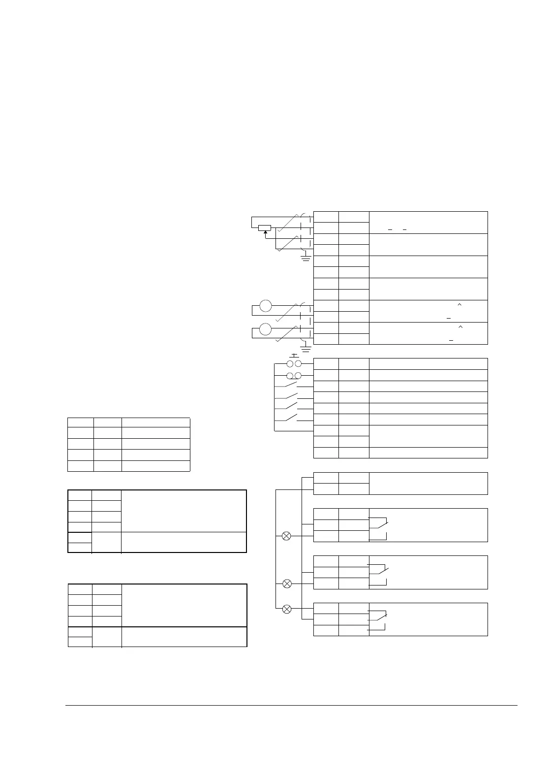
NIOC Board
(A2)
Programmable I/O
Factory Settings
X21
1 VREF Reference voltage 10 V d.c.
1 kΩ <
R
L
< 10 kΩ
2GND
3 AI1+ Speed reference
0(2) ... 10 V
R
in
> 200 kΩ
4AI1-
5 AI2+ By default, not in use.
0(4)... 20 mA
, R
in
= 100 Ω
6AI2-
7 AI3+ By default, not in use.
0(4)... 20 mA
, R
in
= 100 Ω
8AI3-
9 AO1+ Motor speed 0(4)...20 mA
0...motor nom. speed,
R
L
< 700 Ω
10 AO1-
11 AO2+ Output current
0(4)...20 mA
0...motor nom. current,
R
L
< 700 Ω
12 AO2-
X22
1DI1 Start
2 DI2 Stop/Forward/Reverse
3DI3
1)
4 DI4 ACCEL/DECEL 1/2
5 DI5 Constant speed select
2)
6 - Constant speed select
2)
7 +24V +24 V d.c. max. 100 mA
8 +24V
9 DGND Digital Ground
X23
1 +24 V Auxiliary voltage output, non-
isolated, 24 V d.c. 250 mA
2GND
X25
1 RO11 Relay output 1
Ready
2RO12
3RO13
X26
1RO21
Relay output 2
Running
2RO22
3RO23
X27
1 - Relay output 3
Fault (-1)
2-
3-
=
=
2)
Operation: 0 = Open, 1 = Closed
DI 5 DI 6 Output
0
1
0
1
0
0
1
1
Set speed through AI1
Constant Speed 1
Constant Speed 2
Constant Speed 3
1
2
3
5
6
TRANS
Power to link
Link Connections
B-
A+
GND
+24 V
Connector X29 for RS 485 connection
4
FAULT
1
2
3
4
5
6
TRANS
Power to link
Link Connections
GND
B-
A+
GND
+24 V
Connector X28 for RS 485 connection
1)
Parameter 10.3 must be set to REQUEST.
Terminal Block Size
X21, X22, X23, X25, X26, X27: cables 0.5 to 1.5 mm
2
X2: cables 0.5 to 2.5 mm
2
Control Cable Lead-through Size:
Ø: 2 x 3x2...11 mm
Factory settings of application software
selection B (type code):
DI1: Start, DI2: Stop, DI3: Reverse, DI4:
Acc/Dec 2, DI5,6: Constant speed 1 to 3 select.
Fault
A
rpm



 To Next Page