CHAPTER 10 – PREVENTIVE AND CORRECTIVE MAINTENANCE 162
10.5.3 Serial communication interfaces (option)
AF 100 interface
To identify the serial communication
interface in the drive, see the applicable
Wiring diagrams. For further information
on the device, select the appropriate
manual from the list below:
• AF 100 fieldbus - NAFA-01 installation
and start-up guide
• Modbus TCP - NETA-21 remote moni-
toring tool user’s manual
• Modbus RTU - NMBA-01 installation
and start-up guide
• Profibus - NPBA-12 installation and
start-up guide
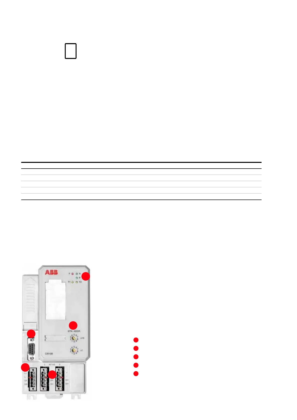
Status LEDs
Service connector
AF 100 station address selectors
Power supply terminals
AF 100 terminals
Table 10-1 AF 100 LED description
LED Meaning
F (Fault) Red Module fault. Also lights up during module start-up. Turns off when the self-test is successful
R (Run) Green In operation
P (Power OK) Green Internal power OK
T1 (Traffic 1) Yellow Data traffic on AF 100 cable 1
T2 (Traffic 2) Yellow Data traffic on AF 100 cable 2