163 ACS2000 AFE 2MVA UM 3BHS355653 ZAB E01 REV. H
Modbus TCP interface
10-6 NETA-21 remote
monitoring tool
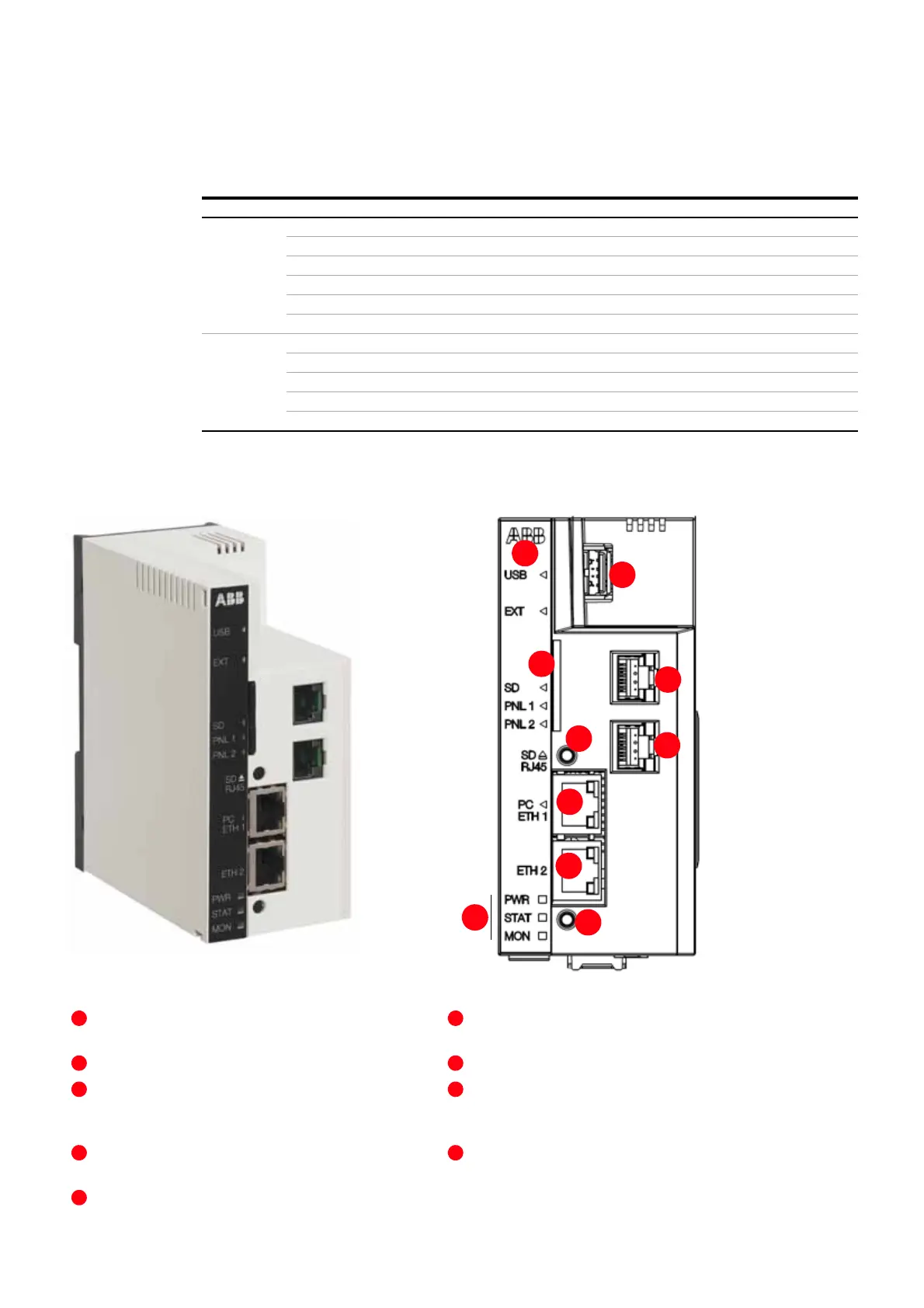
Front panel labeled with a black sticker and equipped
with indicator LEDs.
SD – SD/SDHC memory card slot
SD RJ45 – SD button is used for removing the SD/
SDHC card safely and activating a DHCP server for the
first access to the user interface
PC ETH 1 – connector providing an Ethernet connec-
tion for a locally connected PC
ETH 2 – connector providing an Ethernet connection
for an external Ethernet network
PWR, STAT, MON – power, status and monitoring indi-
cators (see table below for LED indications)
USB – USB host connector for third party extensions
PNL 1/PNL 2 – connector providing an interface for a
panel bus that can be used for communication with
certain drive types
Reset button
Table 10-2 NETA-21 LED description
LED Color Meaning
USB Off No USB mass storage devices attached
Green USB mass storage device attached and mounted
Blinking green Device attached, initialization in progress
Yellow Device can be removed
Red Unidentified error when settings are imported from an USB memory device
Blinking red Initialization failed. Unsupported file system on a USB stick.
EXT Off No NEXA-21 connected
Green NEXA-21 found and initialized
Blinking green NEXA-21 support is being initialized (when the NETA-21 boots up)
Red NEXA-21 malfunctions
Blinking red NEXA-21 not supported
 Loading...


