CHAPTER 10 – PREVENTIVE AND CORRECTIVE MAINTENANCE 178
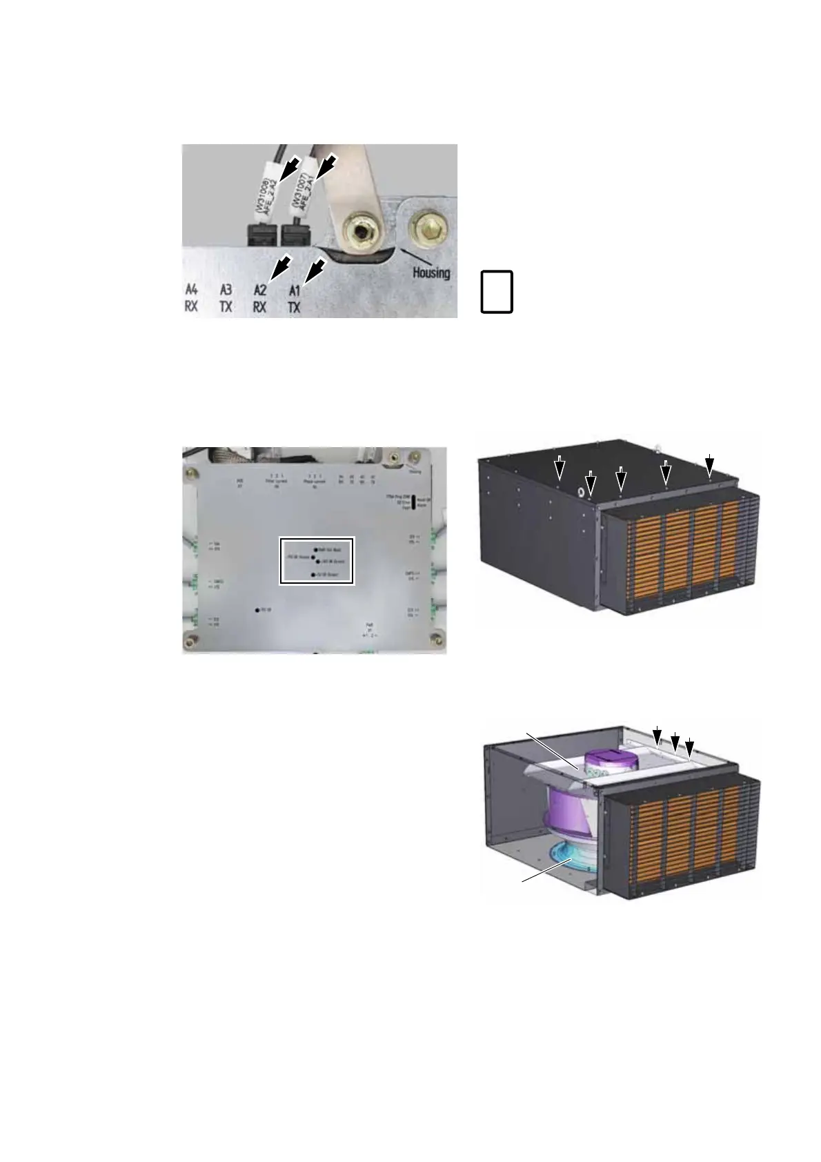
12. When reconnecting the optical fibers, pay
attention to connect them to their correspond-
ing receptacles (arrows).
13. When all cables have been reconnected, check
that the drive control system and the phase
module communicate with each other. Switch
on the auxiliary power supply.
Check that the LEDs on the Phase-INT circuit
board of the phase module are on (box in the
picture below).
14. Push the phase module back into the rack as far
as it goes and tighten the fastening bolt on
each side.
15. Remove the rails and reinstall the acrylic panel.
16. Switch on all miniature circuit breakers in the
control compartment.
The work is now completed, and the drive can be
started again.
For further information, see 8.6 Starting the drive.
10.6.13 Replacing a fan
The fan housing can stay on the roof when only the
impeller is replaced,
1. Disconnect all power supplies to the drive and
ground the drive.
For further information, see 10.6.3 De-energiz-
ing the drive locally.
To isolate the fan unit from the auxiliary power
supply, switch off the motor starter of the fan
unit.
2. Continue with Standard fan units or DTL fan
units as applicable.
Standard fan units
3. Remove the cover from the fan housing.
4. Disconnect the control and power supply cables
of the fan.
5. Remove the fastening screws from the support
plate and the duct ring.
6. Unscrew the support plate from the fan
7. Replace the fan and re-assemble in reverse
order of removal.
To identify the motor starter, see the
Appendix D – Wiring diagrams.