CHAPTER 2 – POWER ELECTRONICS AND CABINET FEATURES 32
2.2 Power supply configurations
The drive requires two independent power supplies:
The following drive configurations are described in
this user manual:
• Main power supply for the power electronic
components
• Auxiliary power supply for the control and cool-
ing equipment
2.2.1 Main power supply configurations
Input transformer
The main power is fed to the drive by the input iso-
lation transformer which adapts the line voltage to
the required voltage for the drive. The input isola-
tion transformer is always part of the drive system.
Two installation solutions are available for the
transformer:
•Integrated
The transformer is placed on the left side of the
drive. The length of the cabinet depends on
drive power. For the integrated configuration, a
dry-type transformer is used.
•Non-integrated
The transformer is external to the drive. The
transformer can either be an oil-immersed or
dry-type device. The distance between drive
and transformer is determined by the maximum
possible cable length for the transformer sec-
ondary cables.
Drives with a non-integrated transformer are
equipped with a common mode choke.
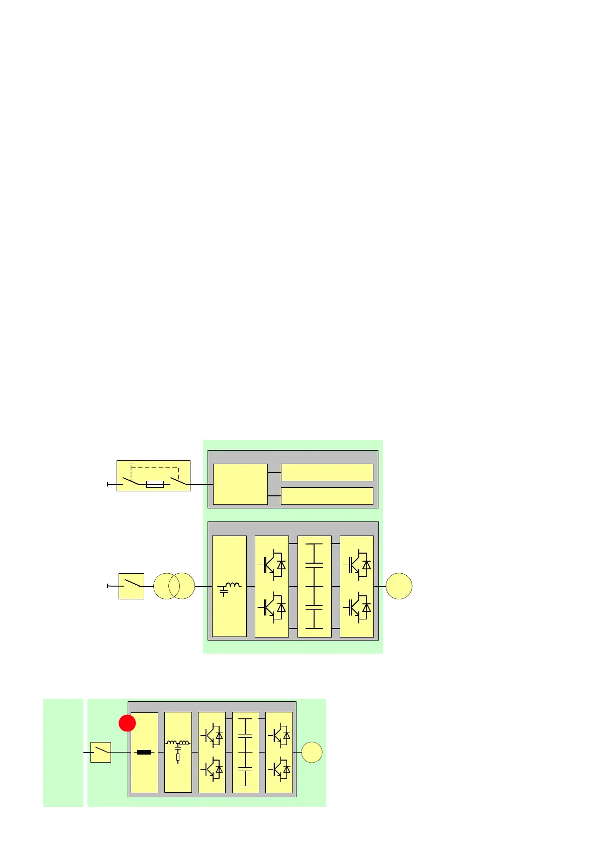
Direct-to-line connection
For applications where the line voltage corre-
sponds to the motor nominal voltage, the drive can
be connected direct-to-line by employing input
reactors (1) instead of an input transformer. The
direct-to-line (DTL) configuration is used for 6 to
6.9 KV line voltages.
2-2 Drive overview with
input transformer
2-3 Single-line diagram of
direct-to-line
configuration
2-2
Power electronic components
Auxiliary
power
distribution
Cooling system
Control system
ACS2000
Auxiliary
Main
Input
transformer
Control and cooling equipment
MCB
power supply
power supply
M
IFU
AFE
DC link
INU
2-3
ACS2000
M
Main
power
supply
1