99 ACS2000 AFE 2MVA UM 3BHS355653 ZAB E01 REV. H
Preparing cables for cable entries with sealing
modules
• Prepare cables with an outer cable screen or
shield for EMC bonding with the metal enclo-
sure of the cabinet as illustrated in 6-6.
• Install the sealing modules according to the
instructions of the sealing module supplier
(Roxtec AB).
6.9.3 Connecting the cables
Checking the cable insulation
• Measure the insulation of each cable before
connection and verify that the results are within
the specification of the cable manufacturer.
• Leave the cable conductors unconnected at
both ends until the commissioning engineer
has given permission.
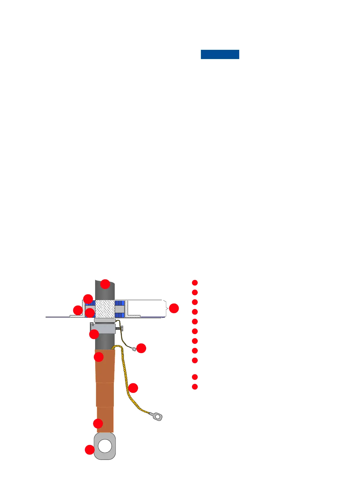
6-6 Preparing power
cables for sealing
modules
Outer cable sheath
Sealing module
Frame
Conductive foil of sealing module
Cable sheath removed to expose cable shield
Cable clamp
Shrinkable sheath seal
Shield extension to be connected to PG busbar
Conductor screen extension to be connected to the
PG busbar
Heat-shrinkable termination
Cable lug as specified by the cable supplier and
suitable for M12 bolt
Risk of flashover!
High voltages will be present in the terminal
compartment. High voltages can cause flashover
between the electric potential of different
conductors, and the electric potential of a
conductor and earth.
Therefore, maintain a minimum clearance of 55 mm
between a conductor and the terminals of any
other conductor, and between a conductor and
earth.